The most frustrating, but also one of the most rewarding things, about making your own guitar pedals is that they rarely work the first time. You spend hours soldering everything, plug it in, and it doesn’t work. Then comes the troubleshooting, finding where your error is, and finally success!
During this troubleshooting and fixing period, you don’t want to permanently wire your new pedal creation into an encloser though. This can hamper the process of finding where you went wrong because your pedal is stuck in an enclosure and you may not have enough room to work. You need something that you can easily connect to that works like a finished pedal, but can be easily detached and re-attached to your work in progress.
And that’s why you need to build a guitar pedal tester.
What’s nice about building a pedal tester is that it’s also a really good beginner friendly project. It’s pretty simple to make, has you soldering, drilling some holes in an enclosure, and it’s easy to make it work. Building a pedal tester is a good candidate for a first project because it’s easy, and then you have something to test all the pedals you’re going to make in the future!
If you’ve built this as a first project and want to actually start building pedals, check out some of the easy guitar pedal builds I recommend.
What Is A Guitar Pedal Tester?
 I’m going to start a little at the end here with the finished product. A guitar pedal tester works just like a regular DIY guitar pedal, but it’s not connected to anything. Typically, a pedal is connected to a circuit that’s soldered onto a PCB or stripboard, it’s then connected to a foot switch that switches the guitar’s signal between the effect circuit and a bypass.
So, all the pedal tester is doing, is creating a pedal with the wiring that usually goes to the effect circuit going nowhere.
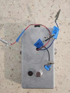
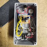
You can see in the pedal tester shown here it looks like a normal guitar pedal, but it has some wires coming out of it. Those wires connect to your newly solder pedal for easy testing. The footswitch and status LED work so you can make sure the bypass is working properly as well.
I’m sure you can appreciate why having one of these things can be so handy. Rather than having to manually wire in input and output jacks as well as your power supply (and ground), you just need to attach the relevant wires via alligator clip for trouble shooting.
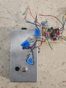
It’s basically a fully functioning DIY guitar pedal with its guts on the outside, as shown below.
And It Works As a Basic Audio Probe Too!
If your pedal isn’t working, it’s likely due to one of three reasons:
- Lack of power to a relevant part of the pedal; here you’ll likely get no signal, a very quiet signal, or a signal with no effect.
- A short circuit somewhere; here you’ll likely get a distorted sound of some sort.
- Audio path incomplete; if there’s a break somewhere in the audio path, you won’t get any sound coming through.
To check lack of power, it’s easy enough to use a multimeter, but to check the audio signal, you’ll need and audio probe. And this tester works well as a basic audio probe too!
To Use This Pedal Tester As An Audio Probe
Using this tester as an audio probe is easy. Simply:
- Attached the 9V power supply, ground, and input wires from your pedal to the alligator clips on the tester. Leave the output from the pedal unattached.
- Clip a long solid core wire to the output alligator clip on the pedal tester.
- Strum the guitar – you won’t hear anything – and use your audio probe at the soldered junction of your input wire on your pedal, you should hear your guitar strum come through.
- Follow the audio signal path with your probe. You may need to strum your guitar as you go to keep sound coming through, but move along the path with your probe.
- Where you lose sound coming through, you’ve found a problem; this may be a bad solder joint, incorrect part placement, etc.
If you’re having trouble finding the audio signal path, check out my guide to finding a guitar pedal’s audio signal path.
Good luck and have fun!
How To Wire A Guitar Pedal Tester
Wiring a guitar pedal tester couldn’t be simpler. If you can wire a guitar pedal footswitch, you can wire a pedal tester. If you’ve never done any of this before, that’s OK. You need to start somewhere. These are things you’ll be doing for pretty much every guitar pedal you make, so why not start with a simple project?
What you will need for your pedal tester build is:
- 3PDT foot switch
- Status LED
- Status LED holder
- 2 x mono guitar jacks
- 9V DC in
- Pedal enclosure
- Solid core wires
Step 1: Drill Out Your Enclosure
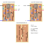
Any enclosure will do here, but there’s no reason to use anything bigger than you need to. I used the standard 125B enclosure that’s commonly used for most DIY pedal builds. Drill out holes for:
- Signal input and output on either side of the enclosure.
- 9V DC in at the top of the enclosure.
- Foot switch towards the bottom in the center.
- Status LED to the right of the footswitch.
- Hole for wires towards the top in the middle.
Assuming you’ve never drilled out a pedal enclosure before, be careful here! Here’s some tips:
- Start with a small drill bit and work your way up. Don’t start with a big bit otherwise you’ll break it and/or hurt yourself. Start small and go up bit by bit.
- You can always make a hole bigger, but you can’t make it smaller. Double check hole sizing with each step. Then put some tape over it when your hole is big enough so you don’t drill it by mistake.
Step 2: Wire Up Your Foot Switch
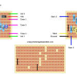
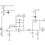
I won’t the full instructions here, but I do have an article on how to wire a guitar pedal foot switch, take a look if you’re unsure. If you’re confident and just want to see a diagram, here it is:
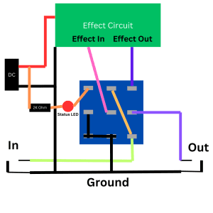
Make sure you’re leaving plenty of excess wire for the parts that go in/out of the effect circuit. In the above diagram, that’s the red 9V wire, one of the black ground wires, the pink wire for effect in, and the blue wire for effect out.
These wires will come out of the hole in your enclosure to attach to your effect.
I’ll say it again: make sure you leave plenty of excess wire. You can always trim it down later.
I also suggest you use sensible wire colours that you’ll understand such as red for 9V, black for ground, green for effect in, and blue for effect out.
Step 3: Attach Components To Enclosure And Solder In Place
With your foot switch wired up, attach everything to your enclosure including your 9V input, your two mono jacks, your foot switch, and status LED.
If you’ve never had to wire up an enclosure before, this is where things may get a little bit tricky because you don’t have as much space to work. Take your time.
Step 4: Feed Effect In/Out, 9V, And Ground Wires Through The Hole
This almost goes without saying, but feed the wires for effect in, effect out, 9V, and ground through the spare hole in your enclosure. Hopefully you’ve left enough excess wire here!
Step 5: Attach Alligator Clips To The Bare Wires And Label Them
Depending on the brand of alligator clip you have will depend on how you attached them, but that’s a pretty easy job.
While you should have used sensible wire colours, it’s also a good idea to label your wires so you don’t get confused in the future. Masking tape comes in handy here.
Step 6: Test Your Tester
Before testing a DIY pedal build, you should test your tester:
- Plug a guitar in as well as a 9V power supply.
- See if the pedal works in bypass (with the status LED off). You should get a normal clean sound.
- Click the switch, the light should go on but you should get no signal.
- Join the effect in with the effect out wire via your alligator clips. You should get a clean sound with the LED on.
- Use a multimeter to ensure 9 volts is coming through the 9V wire.
Step 7: Test Some DIY Guitar Pedals!
Now you can test your latest build quickly and easily.
All you need to do is use the alligator clips to connect to the relevant wire of your newly build effect and see if it works.
If your pedal works, great! You can now wire it into its own dedicated enclosure.
If it doesn’t work, it’s time to test and troubleshoot it. Simply unclip the alligator clips and start the troubleshooting process.

Keep Your Pedal Tester Handy For All Of Your DIY Pedal Builds
Having a reliable tester like this is an invaluable tool for DIY guitar pedal making. You’ll likely use it for every pedal that you make in order to see if it’s working prior to putting it into an enclosure.
As mentioned, this is also a good early project as you’re trying to get into building your own guitar pedals. It’s not too hard but also quickly has something complete.
Related posts:
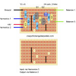 Escobedo Harmonic Jerculator On Stripboard
 Lovepedal Purple Plexi On Stripboard
 ZVEX Super Hard On On Stripboard
 Vox Tone Bender On Stripboard
 Lovepedal Champ On Stripboard
 EarthQuaker Devices Acapulco Gold On Stripboard
 How To Find The Audio Signal Path For A Guitar Pedal
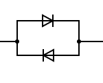 What’s The Difference Between Symmetrical And Asymmetrical Clipping?
 Is It Expensive To Make Your Own Guitar Pedals?
 How Do Guitar Pedals Work?
Just some notes:
1) add this to the Speaker Cranker and the How To Make A Distortion Pedal pages
2) add some gut shots of the test box – the actual pictures next to the various diags would be helpful.
3) add pictures of each component and a diag, but with a link to each page for an expanded explanation.