
As mentioned, don’t forget your input/output jacks, power supply, footswitch etc.
You’ll also need jumper cables for the breadboard build, of course.
Finally, the original Ibanez Tube Screamer (the TS808 at least) used a JRC4558. This is the operational amplifier that everyone talks about and some say is the soul of the Tube Screamer. In actual fact, if you can’t get your hands on a JRC4558 or and RC4558, another low noise op-amp will likely do the job.
Sections Of The Tube Screamer Schematic
If you want a full analysis of the different aspects of the Ibanez Tube Screamer, I highly suggest you take a look at the Electrosmash article. The Geofex article is also an excellent in depth analysis of the Tube Screamer circuit. Those two guys can do a much better deep dive on the pedal than I can. If you want the depth, have a read of those. If you want a general understand of what each section of the Tube Screamer’s circuit does, read on.
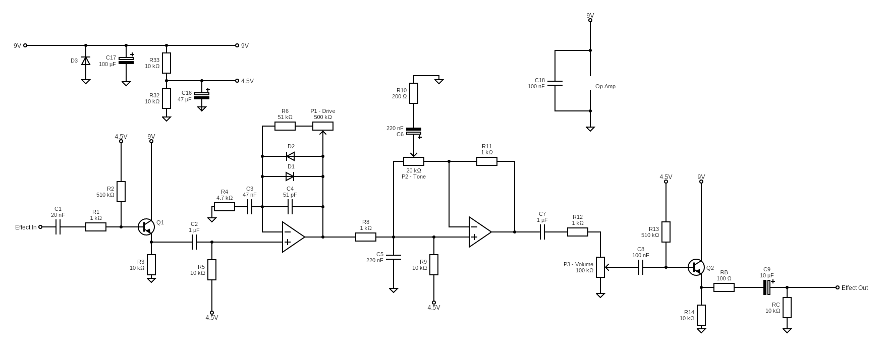
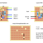
Input And Output Buffer
The input buffer for the Tube Screamer is pretty basic. All they’re doing here is to prevent signal loss, mostly for higher frequencies.
The 4.5V in through R2 is also biasing the signal. Something that’s done again (but not actually needed) in the clipping stage.
For the output buffer, there is some minor loss in voltage, but not enough to really be heard. There’s not much more to say about it!
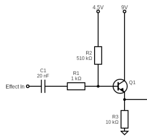
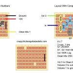
Clipping Stage
The Tube Screamer’s clipping stage is quite standard, but that’s part of the genius of it. There’s no need to do anything special here!
The two diodes are providing symmetrical clipping.
Obviously the total resistance you can get between %6 and P1 is 551k Ohms, just over 100 times more than the output resistor of 4.7K. This is plenty of gain to get clipping from those two diodes.
What’s often missed is that all the resistors and capacitors in this feedback loop also form both a high pass and a low pass filter. This does a lot to give that specific Tube Screamer tone.
According to Geofex, the 4.5 volt bias from R5 isn’t actually needed and doesn’t affect the sound. Analysing the signal on a simulator, you can see that the bias from the input buffer comes through, so the signal is still biased! It’s up to you whether you want to include R5 or not; it could just be another thing that goes wrong…
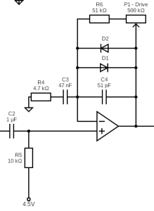
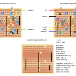
Tone Stage
The main part of the tone control section of the Tube Screamer is basically wo low pass filters. First we get R8 and C5 forming a passive low pass filter. This s designed to generally clean up some of the higher frequencies coming through tat may not sound too good. From there, the potentiometer and C6 form another low pass filter than can be adjusted.
Power Source
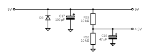
The power supply for the Ibanez Tube Screamer is a pretty standard voltage divider made by R32 and R33. This allows easy access to both the 9 volt power supply for the op-amp as well as the 4.5 volt bias.
D3 provides reverse polarity protection so that things don’t get fried if plugged in backwards while the capacitors smooth out DC voltage dips.
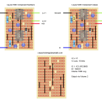
Ibanez Tube Screamer On A Breadboard
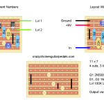
Now, assuming you want to make one of these things, let’s map it out on a breadboard! Here’s a photo of my breadboard layout, but scroll further for a more easy to read digital diagram.
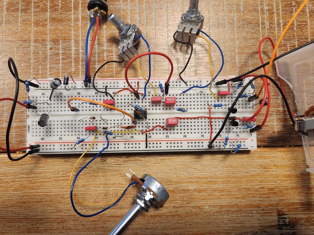
That’s likely pretty hard to read, so I’ve translated it to a digital breadboard.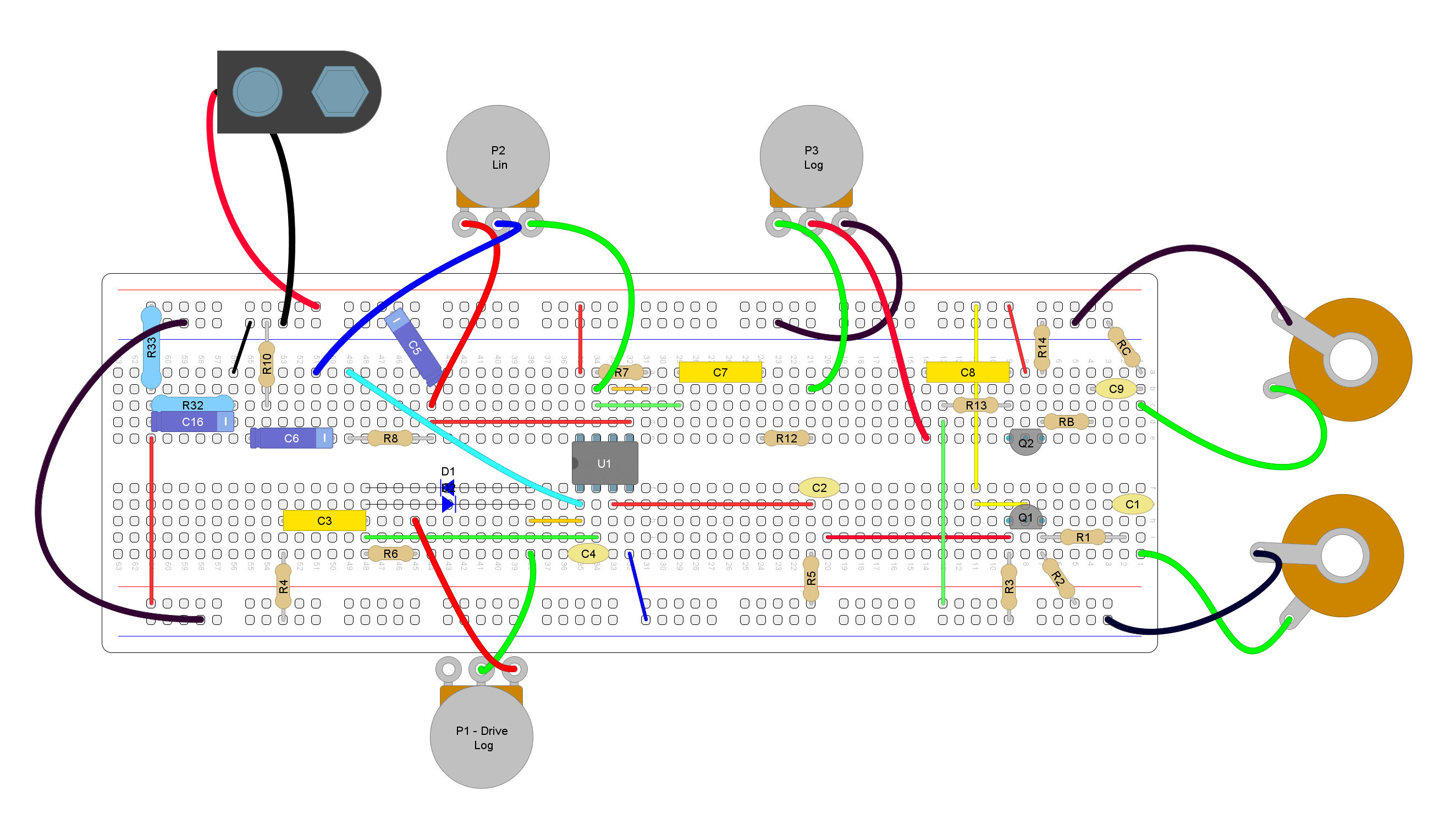
Now that’s probably easier to follow! You’ll notice a couple things.
Firstly, I’ll be the first to admit that there are probably much more efficient ways to build a Tube Screamer on a breadboard. However, this layout puts everything into its own section. It makes it easier to debug if something isn’t working since everything is already isolated. It also makes it easier to modify the circuit because of the isolation.
Secondly, you’ll probably note that I omitted the bias resistors for the op-amp (R5 and R9). As mentioned, these make no difference to the sound and the signal is already biased from the input buffer. Just two fewer things to go wrong.
Thirdly, check out the voltage divider in the top left corner of the breadboard (blue resistors). I’ve jumped this over to the bottom positive row rather; so the top positive is 9 volts and the bottom positive is 4.5 volts. I find this convenient and makes for fewer wires.
Modifications To The Ibanez Tube Screamer
Now that you have your Tube Screamer on a breadboard, why not throw in some modifications to make it your own? While you can’t really improve on perfection, you may be able to tweak the circuit for a more unique sound.
Here’s a few that you may enjoy:
- Add an extra diode in series with D1. This will create asymmetrical clipping. Personally I think this sounds better.
- Increase the gain. You can increase the gain in the clipping circuit either by decreasing the value of R4 or increasing the value of P1. I wouldn’t suggest decreasing R4 since it’s interacting with C3 as an RC filter; lowering R4 will mess with the tone too much. Instead, try replacing P1 with a higher value potentiometer. I jacked it all the way up to 1M Ohms. Up to about 800K it sounded great! From 800-1000K it still sounded fine, but there wasn’t much of a noticeable difference in clipping.
- Change C5 or C6 for different tone. I haven’t tried this one, but if you want to bring in a little more or less treble, changing the values of C5 or C6 will change the low pass filters in these locations.
And That’s A Tube Screamer On A Breadboard
That’s it!
All in all it’s a pretty simple circuit. I like it with a bit more gain and asymmetrical clipping. My next plans are to put the schematic on a PCB with a 1M Ohm potentiometer for gain and a switch to select between symmetrical and asymmetrical clipping. Other than that, there’s not much more to do with this circuit…
Related posts:
 Ibanez Tube Screamer (TS808) On Stripboard
 Lovepedal Champ On Stripboard
 Escobedo Harmonic Jerculator On Stripboard
 Lovepedal Purple Plexi On Stripboard
 ZVEX Super Hard On On Stripboard
 Vox Tone Bender On Stripboard
 EarthQuaker Devices Acapulco Gold On Stripboard
 Greer Amps Green Giant On Stripboard
 Catalinbread Karma Suture On Stripboard
 How To Make A Guitar Pedal Tester And Audio Probe