Also called Veroboard, stripboard was originally made for prototyping electronic circuits. It’s still called Veroboard a lot because it was originally made by a company called Vero Technologies, but a lot of people (like me) use the generic name stripboard.
Stripboard is made of a non-conductive top layer where you place your components and a conductive bottom layer where components are attached to with solder. The conductive bottom layer is laid out in strips of copper (hence the name) so that each row is separate; rows are joined via components attached between them. It’s also possible to break rows by removing the conductive copper, thereby creating different electrical nodes.
How To Use Stripboard And Read Layouts
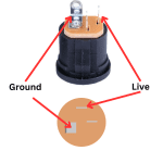
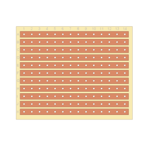 As mentioned, the conductive layer of the stripboard allows electrical signals to pass along it. The picture shown here makes that pretty clear!
However, when using stripboard, sometimes it’s useful break up a row to prevent a signal from passing through. This is good if you don’t need the whole row (but want to use the other part of the row for a different part of your circuit, or with integrated circuits like operational amplifiers that need to be on the same row because of how their pins are laid out.
In this way, stripboard is pretty versatile and, if you’re creative with it, you can fit quite a large circuit onto a relatively small bit of stripboard.
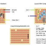
Here’s a diagram of a populate piece of strip board:
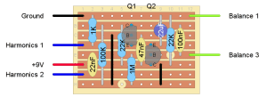
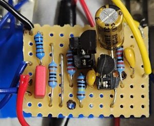
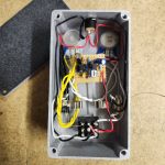
Here you can see where all the components are supposed to go. Although this diagram shows the rows, you’re actually putting the components on the side without rows. The finished product looks like this:
You’ll notice with a stripboard layout, you’ll also be presented with “blank” board that shows where to make cuts and links. Like this:
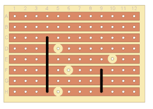
This example has four cuts and two links.
The cuts, represented by the bigger dots, are kind of what they sound like. Here you breaking the conductive strip. You can do this with a drill bit or a knife; just make sure that the break in the conductive strip is complete. Personally, I also like to mark the cuts on the non-conductive side of the stripboard with a dot. It’s a good guide.
The links, represented by the black lines, are attachments between two strips. These are used if you need two strips to connect but not via a component. Most people will just use some bare wire for a link, but you can also use coated wire.
You can also see in the populated example that there are labeled connections coming into the stripboard. This is for things like potentiometers, power supply, ground, and input/output connections.
You can buy stripboard in a variety of sizes, but it typically doesn’t come in the size that you need. The diagram will indicate the size and all you need to do is cut it down. Use a few passes of a sharp blade to do this then sand it so it looks nice.
From there, it’s just a matter of putting pedal components into the right place. Generally, the components on the layout look like their real life counterparts, but if you’re having trouble, here’s everything labelled:
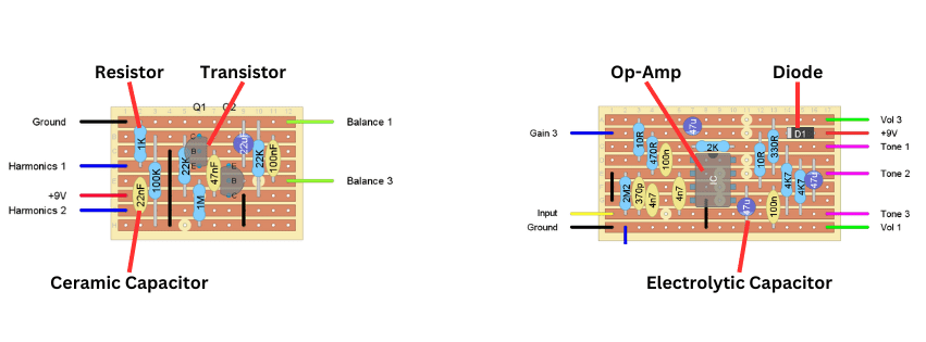
A couple notes:
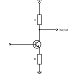
- For transistors, you’ll note that you can see the orientation of the transistor because of how the circular section is facing. Note that (usually) the individual pins for each transistor are also labelled. If you’re swapping out a different transistor, make sure the pins are the same.
- For integrated circuits, usually op-amps, you’ll see that the orientation is indicated by the semi-circle dot (which corresponds with the semi-circle or dot on the real life op-amp). Most of the time, the operational amplifier is oriented with the dot facing north (in relation to the orientation of the stripboard), but this isn’t always the case, so always check.
- Also note the wires coming in for power, ground, input, output, and the potentiometers are labelled as such. Potentiometers in the example are “Harmonics 1,” “Harmonics 2,” “Balance 1,” and “Balance 3.’ This refers to what leg of the pot to wire this connection to.
- In some circumstances there the input or output may be through a pot or the pots are wired together in some way, this will be specified in writing.
- The layout should also specify what kind of potentiometers, transistors, diodes, and ICs to use.
The Advantages Of Using Stripboard To Build Guitar Pedals
Although building a guitar pedal on a PCB is pretty fast and easy, stripboard has its advantages.
Unlike a PCB, you can make almost any circuit on stripboard. This means that if you can find the schematic or stripboard layout for your favourite guitar pedal, you can make it! You don’t need find a supplier of the PCB for that pedal. Obviously pedal PCB kits are great, especially for beginners, but they’re not going to have a board for every pedal ever made.
With that, you can also modify the circuits of your favourite pedals, making additions, subtractions, and substitutions for the components. Learning how to make a layout on a stripboard is a skill in itself, but it’s a worthwhile pursuit.
Going further, if you create your own guitar pedal circuits, it’s usually best to build them on stripboard first. This way you can test the circuit and see how it goes. If you’re only making a few, then staying with stripboard is probably a good idea. If you’re making a bunch, then it may be worthwhile to have to PCBs made.
All in all, stripboard adds some versatility to making guitar pedal circuits. If you’re a hobbyist, it’s all you’ll ever need. If you get more serious, you can move up to making your own PCB.
The Disadvantages Of Using Stripboard To Build Guitar Pedals
Although I personally prefer using stripboard so that I can make all sorts of different guitar pedals, it’s not without its flaws.
The main disadvantage of stripboard is that building guitar pedals (or any circuit) on it is fundamentally slower than building on a PCB. A PCB has everything pre-build and labeled for you, so it’s just a matter of matching the right component to the right hole. With stripboard, you not only need to prepare the board yourself, you also need to make sure you’re putting things in the right place. This takes more time.
With that, stripboard can be a little fiddly. It’s not quite as easy to solder components to stripboard compared to a PCB.
All of this introduces areas where mistakes can happen and therefore it’s more likely your pedal won’t work and you’ll have to debug it, further slowing down your pedal build and introducing frustrations.
Although stripboard layouts can be very compact, since a PCB can have multiple layers to it, a PCB will always win out when it comes to size. And it’s always a good idea to try and make circuits as small as possible in order to fit them into a smaller enclosure!
Related posts:
 Should I Make Guitar Pedals On Stripboard Or PCBs?
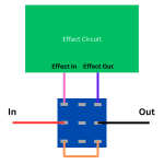
 How To Wire A Guitar Pedal Foot Switch (3PDT)
 What Is A PCB?
 How To Wire A Guitar Pedal DC Power Jack
 How To Wire Guitar Pedal Enclosures
 What Is True Bypass In Guitar Pedals?
 How Do Guitar Pedal (And Guitar) Volume Knobs Work?
 How Does A Drive, Gain, Or Distortion Knob Work?
 Greer Amps Green Giant On Stripboard
 What Is Gain (And How It’s Different From Volume)