Transistors have a variety of applications in electronics, not just in creating guitar pedals. While the use of transistors in guitar pedals is relatively common, they’re not quite as common as components like resistors and capacitors. In a lot of ways, the transistor is often forgotten about in guitar pedal design, as people often think of them as computer components.
And this is because the invention of transistors was integral in the development of modern computing. At their core, transistors act as a simple switch that can control the flow of electricity. These simple switches can work together to create microchips and eventually whole computers.
On the other end, transistors can amplify an electrical signal. In fact, operational amplifiers are just integrated circuits made up of a bunch of transistors. Because of this, with the invention of transistors, amplifiers were able to move away from vacuum tube amplification to solid state amplification using transistors and op-amps.
Because of a transistor’s ability to amplify a signal, and the natural clipping that can occur in transistors, they’re excellent for adding gain to a guitar pedal circuit and therefore distorting the sound of a guitar.
A transistor on a wiring schematic looks like this:
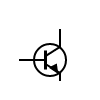 You’ll notice that, unlike a lot of other components you’ve seen, it has three wires. More on this later.
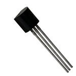
Transistors have three wires, the emitter, collector, and base.
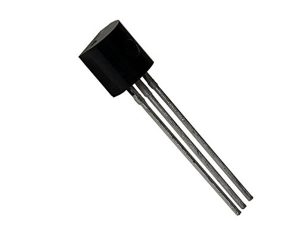
Different transistors will have different pin configurations, so make sure you check the datasheet to confirm how it should be oriented.
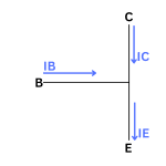
On a wiring diagram, this is how you know which one is which:
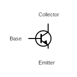
Notice that the base comes straight into the vertical line and the emitter has an arrow on it.
The base of the transistor feeds into the transistor and affects the flow of electrons between the collector and the emitter.
The emitter is called the emitter because it emits electrons (makes sense). Meanwhile, the collector, as the name implies, collects said electrons. It’s the base that aids in this flow.
Transistors come in two major types NPN and PNP. Here the P stands for positive conduction: an area without many electrons. The N stands for negative conduction: an area with lots of electrons.
Electrons naturally want to move from an N layer to a P layer.
This setup means that a change in the middle layer produces a larger change in the current moving through the entire transistor, and this change happens quickly.
Most of the time when building (modern) DIY guitar pedals, NPN transistors are used. But there are plenty of older circuits out there that use PNP transistors and plenty of modern circuits that use PNP transistors as well. More often than not, guitar pedals will use NPN transistors, but it’s far from a rule. Some circuits, like the Harmonic Jerculator, use both!
So how does all this work with the changes in electron flow in the layers and all that?
As a switch, a transistor can rapidly turn off and on depending on whether electricity is flowing into it or not. Put these together and you can make a logic gate. This is more useful in computing than it is in guitar pedal making, but it’s worth noting since we’re talking about how transistors work.
In guitar pedals (and amplifiers), we’re mostly concerned about increasing the signal strength to get more volume or gain. This is done by effectively feeding a larger current into the collector. The signal coming from the base allows current to flow from the emitter to the collector, allowing a stronger signal to come out.
How that amplification happens depends on how the transistor is biased and whether the transistor goes into the active region or the saturation region.
Like diodes, a transistor can clip an audio signal as well.
While diodes have a maximum forward voltage that clips a signal, transistors have a saturation point, and it works in much the same way. If a voltage is put into a transistor that is past its saturation point, that voltage is clipped, distorting the sound.
As transistors add more gain, a certain amount of clipping is expected. If you’re trying to make a clean amp, it’s a matter of balancing the amplification with the amount of clipping that happens. Fortunately when when guitar pedals (DIY or otherwise), we want this clipping! So the balancing acts is about how much gain is added.
The amount of gain that a transistor gives is called hFE or beta, and how this gain interacts with the voltage will not only define how loud the transistor gets, but also where and how it clips at its saturation point.
As mentioned, a transistor will naturally clip a bit. And since op-amps are essentially made up of transistors, they also naturally add a bit of clipping. We can increase this gain by strategically adding resistors.
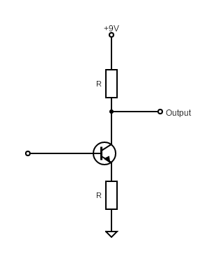
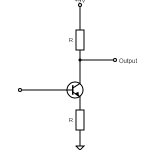
You can add a resistor below the emitter and have it go to ground, or you can add a resistor above the collector going toward the power source, as shown in the diagram below.

Increasing the resistance going to ground decreases the gain and therefore clipping while a resistor going to the power source increases the gain and therefore clipping. There’s a lot of different ways to adjust gain by balancing resistors. It’s not just a matter of putting a really big resistor connected to the power source and blowing everyone’s ears off. It’s a balancing act and making a decision about where to put the potentiometer to adjust the resistance value.
Learn more about transistors and other guitar pedal components.
When talking about transistors used in guitar pedals, we’re usually talking about germanium and silicon transistors. In researching this article, I was trying to find out about different kinds of transistors and I kept getting information on NPN versus PNP transistors and bipolar junction transistors (BJTs) and field effect transistors (FETs) and more. I’m not going to go into the latter here. NPN bipolar junction transistors are the most common in guitar pedals, but other types are transistors are also pretty common. That being said, JFETs, MOSFETs, and BJTs is another conversation to have, and something to discuss in a another article.
So when asking, what are the different kinds of transistors used in guitar pedals, I’m only going to talk about germanium and silicon transistors.
Germanium transistors typically have lower gain than silicon transistors and, because of that, tend to have a smoother clipping and wider sound.
This is a classic transistor gain sound, and some people swear by it. You’ll do fine with silicon transistors, but if you can get some germanium transistors to play with, why not?
Silicon transistors have higher gain and can result in a more clipped and compressed sound.
You can get silicon transistors in a variety of gain ranges though (I, of course, have not tried every transistors out there).But it’s not just the gain ranges that effect the sound of transistors.
There are some material differences between silicon and germanium transistors, how they act, and how they sound. It just depends on what you’re going for.
This is a question as old as time…
As mentioned, germanium transistors are said to have a more vintage sound while silicon transistors have a more modern sound. There’s no transistor that’s “better,” it’s just that silicon clips more. You may like it, you may not.
I encourage you to create a simple gain circuit with transistors and have a listen for yourself.
Transistors are a bit hard to get your head around when understanding how they add gain to a guitar pedal circuit. I’ve done my best to explain them! At the very least, it’s clear how to increase and decrease gain in your circuit.
As mentioned, make a simple gain circuit with some transistors and vary the values of resistance. You’ll understand what’s going on quickly.
 What Is Transistor hFE?
 The Difference Between Silicon And Germanium Transistors
 The Difference Between NPN And PNP Transistors
 Ultimate Guide To Resistors In Guitar Pedals: What They Do And How They Work
 Ultimate Guide To Diodes In Guitar Pedals: What They Do And How They Work
 Transistor Saturation, Active, And Cutoff Region
 What Is Gain (And How It’s Different From Volume)
 What Are Coupling Capacitors?
 How Does A Drive, Gain, Or Distortion Knob Work?
 What Is True Bypass In Guitar Pedals?