What Is A Resistor?
A resistor adds resistance to an electrical circuit. There we go, article done. Now you know everything you need to know about resistors, right?
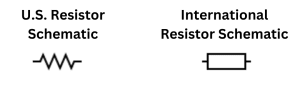
While that’s pretty obvious, it’s useful to know what resistance is and what exactly it does in an electrical circuit, especially the electrical circuit of guitar pedals. If you look at a wiring diagram, you’ll see that a resistor is represented by the symbols below (U.S. on the left and international on the right) and that there are often lots of them in a guitar pedal circuit.
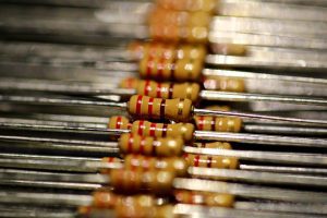
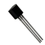
In real life, a resistor looks like this:
So what is resistance? Resistance refers to the flow of current in a circuit. So the more resistance is added to a circuit, the lower the current will be. This is shown in Ohm’s Law that states:
Reading A Resistor’s Value
Reading a resistor can be a bit of a pain.
You’ll have probably noticed by now that every resistor has a number of coloured lines painted on it. These coloured lines can be translated into what the resistance value of that resistor is. It takes some practice, but it eventually becomes second nature to compare the lines on a resistor to a chart outlining what everything means. Over time, you may even memorise it!
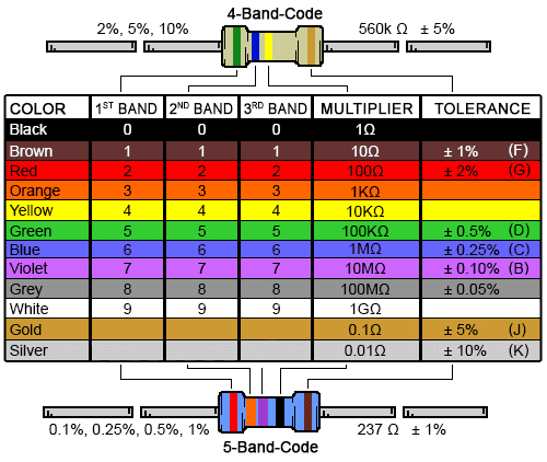
Diagram from DigiKey.
If you’re having trouble working with the diagram, DigiKey have an excellent online resistor calculator. I use it all the time.
Pro tip: even with a diagram in front of you and an automatic calculator, it can still be difficult to read resistors. If you’re anything like me you’re probably making your own DIY guitar pedals in your garage where the lighting isn’t too good. Because of this I like to stay organised and keep all my resistors sorted into different boxes so I don’t have to read them so much.
Understanding Resistors In Parallel And In Series
Resistors (and electrical components in general) can be described as in parallel or in series, and they act differently depending on whether they’re in series or parallel.
Resistors in series look like this:
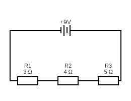
When put in series, the total resistance is simply the sum of all the resistors together.
This works for any amount of resistors in series. Just add them all up!
Resistors in parallel look like this:
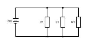
Resistors in parallel behave a bit differently from resistors in series. To find the total resistance in a circuit with resistors in parallel, the equation is:
What Do Resistors Do In A Guitar Pedal?
I’ve already mentioned that resistance can allow you to control the current and voltage in a circuit. Because of this, having strategically placed resistors in a guitar pedal circuit allows you to do quite a lot!
Generally Adjusting The Input And Output Level Of The Pedal
A resistor can be used to adjust the overall amplitude (i.e. strength) of a signal coming out of a guitar and into a guitar pedal or the strength of the signal coming out of the pedal and into an amplifier. This can be a good thing for if you need to lower the signal going in or out of a pedal.
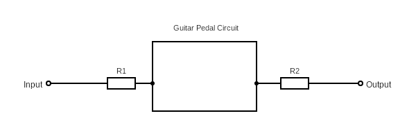
There will be more on this later, but if you want to adjust the volume of a guitar pedal, all you need to do is give it more resistance on the output!
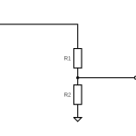
Voltage Dividers
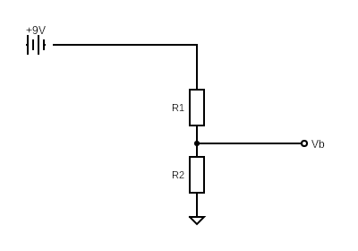
One place you’ll often see resistors is in the use of a voltage divider. Since voltage drops across resistors in series, two resistors can be used to drop the voltage in a circuit to a desired number. This comes in handy for things like biassing an op-amp.
But put it simply, although we typically use a 9 volts power input in guitar pedals, we don’t always want 9 volts for every part of the circuit. Because of this, we can use voltage dividers to put the desired amount of voltage through a circuit.
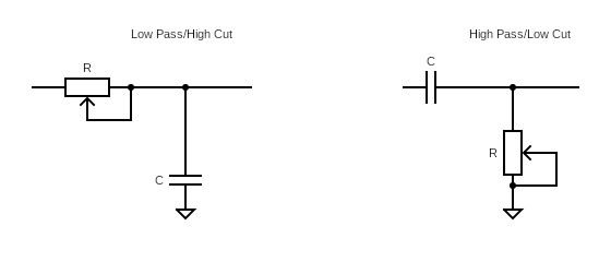
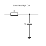
Low Pass And High Pass Filters
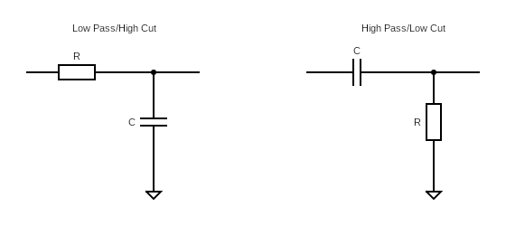
Low pass filters, also sometimes called high cut filters do what they sound like: they allow lower frequencies to pass through while cutting out higher frequencies. High pass/low cut filters do the opposite; these filters allow high frequencies to pass through while cutting lower frequencies.
A low pass and high pass filter is made through pairing a resistor and a capacitor in series and sending the filtered frequencies to ground. If you put the resistor first, you have a low pass filter. If you put the capacitor first, you have a high pass filter.
To calculate where the frequency drop off is, use the equation:
Where R is resistance and C is capacitance.
Low pass and high pass filters are how the specific tone of a guitar pedal is shaped. Different pedals will use different low and high filters to shape the specific tone of their pedal. In fact, playing with resistors in standard pedal builds can be a fun way to mod pedals. Change up resistors in pedals you’ve made (or are happy modding) and see what it does to the tone!
I have a whole guide to guitar pedal high and low pass filters if you need more information.
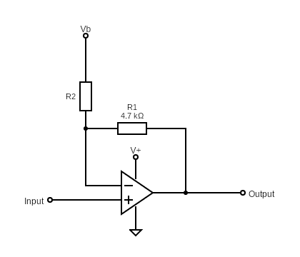
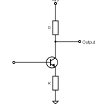
Adding Gain Through An Op-Amp Or Transistor
I’m not going to go into the ins and outs of how operational amplifiers work (op-amp) and how transistors work, but the long and the short of it is that a resistor in the feedback loop of the op-amp, as well as a resistor going to ground is how gain is created.
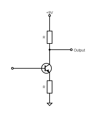
Using a transistor to create gain , on the other hand, is also common. A transistor can have a resistor connected to the emitted and going to ground and/or have a resistor connected to the base to control the gain. A resistor connected to the emitter going to ground creates less gain with a bigger resistor while a resistor connected to the base and going to the power source creates more gain with a bigger resistor.
Gain increases the signal that’s coming through the guitar, adding more volume to the signal and, if you clip that signal, overdrive and distortion!
Pulldown Resistors
On guitar pedal wiring diagrams, you may see “random” resistors coming off the main circuit and going to ground and wonder what these are doing. These are referred to as pulldown resistors.
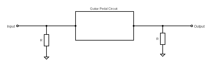
Pulldown resistors are used to reduce noise when the guitar pedal is turned on. Noise can occur in the form of a “pop” when a pedal is turned on because residual voltage can stay in the circuit, especially in capacitors. These pulldown resistors help to drain the circuit of this voltage and send it to ground.
You’ll notice that pulldown resistors are often of a big value like 1 Mohms and are placed at the beginning and end of the circuit in a guitar pedal. This makes sure that that little bit of voltage mostly goes through these resistors when the pedal is turned on.
What’s That Random Resistor Doing?
If you’re looking at a wiring diagram and see a resistor that just looks random, it most definitely has a purpose! It may not be immediately obvious or clear because a full circuit diagram has more going on in it than the basic schematics show here.
Try to isolate sets of components so that they “become” what you’ve seen before. Odds are, a resistor is doing one of the things listed above.
Potentiometers As Variable Resistors In Guitar Pedals
Beginners don’t often realise it, but a potentiometer is just a variable resistor.
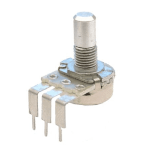
By moving the dial on a potentiometer, you’re just varying the resistance that’s flowing through the circuit.
Because of this, if you put a potentiometer into any of the diagrams shown above, you’re creating the same effect whether that be a signal strength, high pass/low pass filter, or gain control.
Let’s quickly look at how.
Volume Potentiometers
A volume potentiometer is very simple. As I already mentioned, resistors are often put at the start and end of a guitar pedal circuit to modify the strength of a signal. By making this end of circuit resistor variable with a potentiometer, you can then adjust the volume.
Tone Potentiometers
To remind you, a high pass and low pass filter looks like this:
By adjusting the amount of resistance in the filter, you can adjust the cutoff frequency of the filter. So, rather than using a resistor with a static amount of resistance, you can use a potentiometer to adjust the amount of resistance in the filter and therefore adjust the tone.
It’s pretty simple, isn’t it?
Gain Potentiometers
Finally, we have potentiometers used for gain control.
Whether you’re using an op-amp or a transistor for gain, both of these components rely on a resistor to adjust the amount of gain created. So again, rather than using a static resistor, use a potentiometer to adjust the gain.
Summing Up
Resistors in guitar pedals can seem like a bit of a mystery. When I first started looking at wiring diagrams, the resistor placement looked kind of arbitrary. Then you also start wondering why certain values are used.
But really, resistors are quite a simple part of guitar pedal design. By controlling the voltage and current in the circuit, you can do a lot and make some really awesome sounds.
Whether you haven’t started building yet, or you’re starting to modify standard designs, have a play with different resistor values and see what they do to the sound. And have fun!
Related posts:
 Ohm’s Law: Explanation And Applications
 Ultimate Guide To Diodes In Guitar Pedals: What They Do And How They Work
 Ultimate Guide To Transistors In Guitar Pedals: What They Do And How They Work
 How High Pass And Low Pass Filters Work In Guitar Pedals
 What Is A Voltage Divider?
 What Is Transistor hFE?
 How Do Guitar Pedal (And Guitar) Volume Knobs Work?
The Difference Between Silicon And Germanium Transistors
How Do Guitar Pedal (And Guitar) Volume Knobs Work?
The Difference Between Silicon And Germanium Transistors
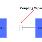 What Are Coupling Capacitors?
 How Does A Drive, Gain, Or Distortion Knob Work?