I’ll cut to the chase very quickly: you’re probably here because you want to learn how to make guitar pedals at home, so you searched for something along the lines of “how to make a distortion pedal,” and found this website. Welcome!
The good/easy part of answering that question is, sure, read on and I’ll give you a step by step guide on how to build a simple distortion pedal at home. The bad/hard part of answering that question is figuring out how knowledge readers have before coming here and also figuring out how much information readers wants for context: i.e. do readers just want the steps without understanding the why of it? How much should I explain things?
So I’m going to come at this article assuming you know nothing. This doesn’t mean there will be lengthy explanations for everything though. Instead, I’ll give brief explanations with links to relevant resources as needed.
For this tutorial on making a distortion pedal yourself, I’ll be using the stripboard design for the Speaker Cranker by EarthQuaker Devices. Some (including EarthQuaker Devices themselves) are referring to the Speaker Cranker as an overdrive, and while there are some obvious differences between overdrive and distortion, there’s also sometimes a fine line, and this is a pedal that’s one of them.
If you’re confident with building a guitar pedal on stripboard, you can also skip all of this and check out my general write up of how to make an EarthQuaker Devices Speaker Cranker on stripboard. This is the full guide; the link is just the layout with my experience.
What You Need To Build A Distortion Pedal
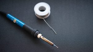 I have a whole article on the gear you need to build guitar pedals, have a read of it if you’d like a bigger explanation of everything, but in short, what you’ll need before you start includes:
- Components to build your guitar pedal including resistors, capacitors, transistors, diodes, wire, etc. I’ll go into sourcing components later.
- Stripboard: this is what you’ll be building the distortion pedal on.
- Soldering iron
- Solder – I suggest 0.6-0.8 mm lead free solder.
- Blu Tack – it helps hold down your stripboard.
- Wire cutters
- Wire strippers
- Long nose pliers
- Solid core wire – I prefer 22 gauge solid core wire
- Drill and bits – if you intend to put your newly built distortion pedal into an enclosure.
The biggest hurdle to getting started with making your own guitar pedals, in my opinion, is the soldering iron. Most people have the other gear that’s needed to get started, and consumables like stripboard, solder, and wire are cheap. Get a soldering iron within your budget then upgrade it later if you get into the hobby.
Sourcing Components For A DIY Distortion Pedal
As a newbie, you probably have no clue where to get components for the distortion pedal you’re about to make. And that’s OK. When I first got started with this hobby, I realised that some of the parts, particular the transistors and op-amps, are pretty specific and not always carried by my local electronics store.
For almost all of my components, I order from Tayda Electronics. They’re based in South-East Asia so, depending on where you are in the world, you may find shipping a little expensive, especially when you’re only paying a couple cents for some components, but they’re fast, reliable, and generally have what you need.
In terms of specific components for this distortion pedal build, I’ll list all the component values individually, but if you’re curious, you can read more about each component in the link below:
- Resistors – look for resistors with the correct resistance value that are listed as “1/4W 1% Metal Film Resistor.” Feel free to read the article to understand what that means.
- Capacitors – the capacitors in this build come in two flavours.
- Ceramic disc capacitors – anything rate between 10 and 50 volts is fine (lower voltages are smaller). 50 volts seem to be the most common, but if you can find something lower, that’s better (just stay over 10 volts).
- Electrolytic capacitors – again, keep the voltage low, as long as it’s over 10 volts.
- Diodes – get the model number listed.
- Transistors – get the model number listed.
- Potentiometers – you want “PCB mount” potentiometers with the resistance specified in the parts list.
- Solid core wire – AWG 22 is what you want. Get 30 cm of a 5 or 6 different colours.
From there, you also need a footswitch, power jack, enclosure, and input jacks. On Tayda, look for:
- DC Power Jack 2.1mm Enclosed Frame – this is your power input.
- 6.35mm 1/4″ Mono Chassis Socket / Jack – input and output jacks for guitar leads.
- 3PDT Stomp Foot / Pedal Switch – stomp it and make loud!
- 125B Style Aluminum Diecast Enclosure – the enclosure to hold your pedal.
- LED 3mm Red – so you know it’s on or off.
- 3mm Bezel LED Holder Chrome Metal
There is a list below with the total amounts of everything you need, but I figured I’d outline what everything is here and be specific on types.
Order The Parts From Tayda:
Here’s exactly what you need from Tayda:
For the pedal itself:
- 330R resistor – 1
- 2K2 resistor (may be listed as 2.2K) – 1
- 10K resistor – 1
- 1M resistor – 1
- 2M2 resistor (may be listed as 2.2M) – 1
- 68n ceramic disc capacitor – 1
- 100n ceramic disc capacitor – 1
- 100u electrolytic capacitor – 1
- 1N60P diode – 3
- 2N3904 transistor – 1
- 5K linear potentiometer – 1
- Solid core wire – five or six colours, 30 cm of each
For the enclosure:
- DC Power Jack 2.1mm Enclosed Frame – 1
- 6.35mm 1/4″ Mono Chassis Socket / Jack – 2
- 3PDT Stomp Foot / Pedal Switch – 1
- 125B Style Aluminum Diecast Enclosure – 1
- LED 3mm Red – 1
- 3mm Bezel LED Holder Chrome Metal – 1
- Knobs (for potentiometers) – 1
Keep in mind that resistors and capacitors are pretty cheap, you may only be able to get them in packs of 10, but that pack of 10 will be about 10 cents, so you’re OK. If you get into this hobby, you’ll quickly figure out what you go through the most and order in bulk. If you’re super keen, check out my other easy guitar pedal builds and buy enough components for 2 or 3 pedals!
Building Your DIY Distortion Pedal – The Stripboard Layout
OK, so that was background information. Let’s get building.
Below I’m going to present a stripboard layout and walk you through it. I’m not going to go through what everything does, you probably don’t want or need that right now. Concentrate on building this first distortion pedal and, as you get more and more into it, you can learn more about all the components. I’ve linked throughout this article to introductory resources if you’re curious.
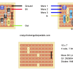
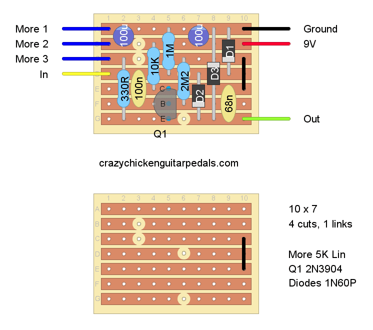
Here’s the stripboard layout for the EarthQuaker Devices Speaker Cranker. Click on the image if you need to enlarge it.
That layout may be all well and good, but if you’ve never built a guitar pedal before or followed a stripboard layout, it probably means nothing to you. Let’s work through it and how you’ll construct this thing.
Step 1 – Cut Your Stripboard To Size
The stripboard required for this pedal is 10 x 7; i.e. 10 holes wide and 7 holes high. Remember that orientation is very important here, as the strips of conductive material go horizontal, not vertical.
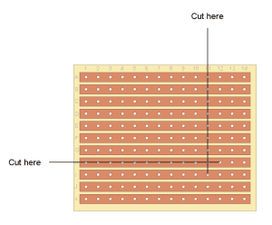
To cut the stripboard, count out the right size then go at it with a sharp Stanley knife. I usually cut the adjacent holes, rather than try to cut between holes. So, for stripboard that needs to be 10 wide, cut across the 11th holes.
Step 2 – Create Cuts And Links
You’ll notice that the diagram calls for 4 cuts and 1 link. The stripboard layout has the layout with all the components on the top, and the layout with just the cuts and links below (so you don’t miss any). The cuts are shown as the little circles and the link as a black line.
- Cut: a break in the conductive layer on the back on the stripboard.
- Link: a wire link between two rows of conductive layers.
Cut and link positioning (IMPORTANT):
The stripboard diagram above makes it look like you’re looking at the stripboard from the side with the conductive strips. This is for reference only. The positioning of the cuts and links are from the perspective of looking at the stripboard from the non-conductive size.
I like to use a permanent marker to first mark the top left corner of the stripboard (from the non-conductive side) so I know which way is “up.” From there, I mark the positions of the cuts with the permanent marker and then make the cuts on the conductive side by sticking some wire through to find the right hole.
The marked cuts on the non conductive side of the stripboard make good reference points for other components. But remember, measure twice, cut once.
To make a cut:
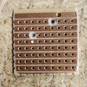
Use a Stanley knife or small drill bit to completely remove the conductive layer for that hole. What you’re doing is creating two rows of conductivity that aren’t touching (and therefore can’t send electricity through).
To make a link:
A link is just a wire connecting two rows.
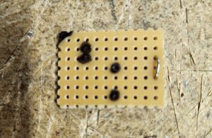
Strip the plastic off some of your solid core sire and solder it into place. All components (including the links) are placed on the non-conductive side of the stripboard, with the wire poking through the relevant hole and then soldered onto the conductive strip.
Here’s an example of a link (the metal bit on the right on the stripboard). It’s also what you unpopulated stripboard should look like.
Step 3 – Solder The Components Into Place
Now it’s time to start soldering components into place. Take a look at my how to read stripboard layouts article if you’re stuck on anything, but mostly the components in the layout look like the components in real life.
That being said, here are some tips:
- Use the Blu Tack to hold your stripboard in place.
- Solder in “flatter” components first. My preferred order of placing components on the board is resistors, diodes, ceramic capacitors, electrolytic capacitors, transistors, wires for input/output, potentiometers, etc.
- It’s possible to damage your transistor with too much heat. Consider using an IC socket (look for it on Tayda).
- If you ordered everything listed above, you will wind up with a spare 2.2K resistor. This is for the status LED that you’ll wire into your enclosure.
Orientation matters for:
- Electrolytic capacitors: notice how the layout has a dark circle with a small white line; so does your electrolytic cap in real life. That’s the orientation that’s needed.
- Diodes: notice how the layout has a solid colour, with one end a different colour. So do your diodes.
- Transistors: your transistor should be shaped like a semi-circle, it should have the same orientation as shown in the diagram.
Wires and potentiometers:
You’ll notice lines coming out with “More” 1, 2, and 3; as well as lines for “In,” “Out,” “Ground,” and “9V.”
These are wires for power, input/output, and the one potentiometer (pot) for this pedal.
- For all the wires, make sure they’re long enough for when you box the pedal up. It’s easier to make them a bit shorter than to try and extend them.
- For the potentiometer, “More 1” refers to the first leg of the pot, etc. The legs are numbered left to right if you look at the pot straight on with the knob pointing upwards. More information on how to wire a potentiometer if you want it.
Test And Debug Your Pedal
It’s time to test your pedal to make sure it works before boxing it.
To do this, you need to temporarily wire up your input/output jacks and your power. I won’t give a full rundown on how to do it here because I already have these resources:
In relation to these, the wire marked as input on the stripboard layout goes to the live part of the input socket (coming from your guitar); the wire marked as output to the live part of your output socket (going to your amp).
Also keep in mind that ground is shared, so all ground wires (i.e. from the sockets and the pedal) need to go back to the ground of your DC jack.
If you’re lucky, your pedal will work first time (yay!), if not:
- Double check the wiring for your sockets and power jacks.
- Check your soldering for any short circuits: is anything touching that shouldn’t be?
- Check the orientation of your transistor, capacitors, and diodes.
- Go through my DIY guitar pedal debugging guide.
Debugging and fixing DIY guitar pedals is just part of the hobby. You’ll find it.
Put Your Guitar Pedal In An Enclosure
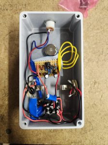 From here, it’s time to put your new pedal in an enclosure so you can turn it off and on and actually use it.
Wiring guitar pedal enclosures can be a bit fiddly, but if you’ve successfully gotten your distortion pedal circuit working, wiring up the enclosure is the easy part.
I won’t go through all the steps again because, like other sections of this how to, I already have a resource:
The above will take you through all the steps of wiring in input/output sockets, power, your footswitch, etc. Take your time with it and you’ll have great looking guts for your new pedal.
After your pedal is in its enclosure, plug it in and piss off the neighbours! You’ll notice that the Speaker Cranker only has one knob on it (obviously), but it’s a good first step towards more complex builds. The “more” knob kind of does what it says: it gives you more. You’ve just built your first guitar pedal, soon you’ll be making stuff with pots for volume, gain, tone, and more.
DIY Guitar Pedal Resources
Obviously I’ve written this guide for the complete novice. I’m assuming that you’re coming into this with absolutely zero knowledge on making guitar pedals. I purposefully haven’t gone into any theory on how things work, but if you’re interested, you can find this information.
So whether you need help or want more information, there are plenty of resources out there:
- My guides to guitar pedal components if you want to understand what something does.
- My beginners guide to DIY guitar pedals for a bit more depth on what you’ve found here.
- Reddit DIY Pedals – most questions can be answered there.
- Tagboard Effects – more stripboard layouts than you can count. Find something you want to build, if you have trouble, the comments section is pretty good.
Building More Guitar Pedals And Growing Your Hobby
So, you’ve just finished your first guitar pedal, well done! If you want to build more, it’s really just a matter of finding the stripboard layout of something you’re interested and ordering the parts. Alternatively, you can also get PCB kits that make things a little easier, but are a bit more limited as to what’s available.
I linked to Tagboard effects above, but also check out my easy DIY guitar pedal builds, you really can’t go wrong with any of them, and they’re great for beginners. As you grow, check out my other DIY guitar pedal stripboard layouts. I’ve taken most of the layouts from other sources on the internet, but find those sources just present the layout without much other information; I’m building the pedal and then providing some extra information if you need it.
Anyway, that’s one hefty article I’ve just written. Welcome to a new hobby. Enjoy it.
Related posts:
 Greer Amps Green Giant On Stripboard
 EartherQuaker Devices Speaker Cranker On Stripboard
 Lovepedal Purple Plexi On Stripboard
 ZVEX Super Hard On On Stripboard
 Lovepedal Champ On Stripboard
 EarthQuaker Devices Acapulco Gold On Stripboard
 Building A Simple Distortion Pedal Based On The Electra Distortion
 Vox Tone Bender On Stripboard
 Catalinbread Karma Suture On Stripboard
 ProCo Rat On Stripboard

It would be cool to see how some of these could be laid out on a breadboard?
Thanks for the feedback Fred – it’s not the same, but a similar circuit and breakdown is here (https://crazychickenguitarpedals.com/guitar-pedal-blog/guitar-pedal-builds/how-to-make-a-distortion-pedal/). I’ll make a breadboard diagram of the circuit in this article though as well – it’s on my to do list now!