Note: This article is meant to accompany the video above. It’s not a transcript of the video, but more a way to more easily see the diagrams I’m using in the video so that you can build an Electra Distortion yourself on a bread board. You’re welcome to read the article without watching the video, or vice versa. Or do both!
The Electra Distortion is a nice little distortion circuit that sounds great and is also really easy it make. It’s the basis for more than a few easy to make guitar pedals, so I thought it would be interesting to explore it a little bit and build out a basic full featured distortion pedal. I’m not aiming to design the world’s best distortion pedal, just explain the circuit and how to build out gain, tone, and volume control.
If you have a few guitar pedal builds under your belt and want to better understand what everything’s doing, this article and video is a good primer to see things happening in real time without having to read all of my guitar pedal component guides.
The Basic Electra Distortion Circuit
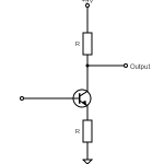
The basic Electra Distortion is pretty basic, but it works well and sounds pretty good for not a lot of components.
As you can see, there’s not much there…
As explained in the video, all that’s happening is the guitar signal is going in, getting amplified by the the transistor, and then being clipped by the diodes. I have an explanation of how transistors amplify a signal and how clipping diodes work if you’re interested in understanding more, but if you just want to know the basics: transistor amplifies, diodes clip. The resistors are there to control the amplification of the transistors and the capacitors are there to prevent DC leakage.
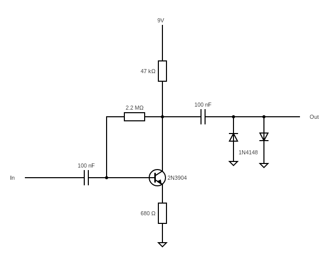
If you want to build this circuit on a bread board so you can hear how it sounds, here’s the diagram:
If you watch the video, build this yourself, or just see it, you’ll notice that there’s no way to adjust the amount of distortion in this circuit. This is a feature of the Electra Distortion. To adjust how much distortion you get out of this circuit, all you need to do is adjust the volume on your guitar. Lowering the volume on your guitar restricts the signal strength into the circuit, thereby making the clipping less.
So how do you make it so you can adjust the clipping from the pedal itself? Let’s take a look.
Adding Gain Control To An Electra Distortion Circuit
There’s a couple ways to add gain control to a circuit like this.
Basically speaking, the amount of gain a transistor gives (and therefor how much is amplifies a signal) is a function of the ratio of the resistors coming out of the collector and the emitter; so in the schematic above, it’s the 47K and 680R resistors. Changing these values will change how much the transistors amplifies.
So, one option to adjust the gain for this pedal, would be to add a potentiometer in place of the 680R resistor.
Another option is to restrict the signal coming into the circuit, similar to how you do it with the volume pedal on the guitar. This is done using a potentiometer.
For the purpose of this article, I’ve chosen to simply restrict the signal coming into the circuit. Replacing the 680R resistor with something like a 1K potentiometer would probably work better, but I felt it kind of got in the way of understanding the bread board layout.
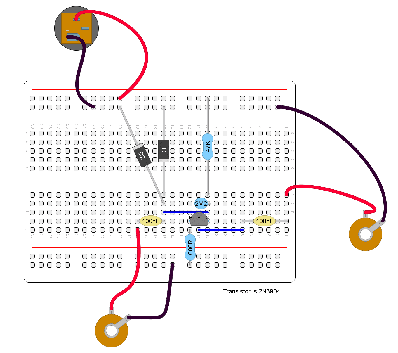
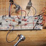
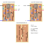
Adding the extra pot looks like this:
In this layout, the potentiometer is actually backwards, i.e. if you turn it counter-clockwise you get more distortion and clockwise less, but for teaching purposes it makes it easier to show on the breadboard. If you want it the “right” way around, turn the pot around of swap the left and right wires.
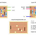
Adding Tone Control To An Electra Distortion Circuit
Adding tone control to this circuit is quite simple. All you need to do is add a low or high pass filter after the clipping stage of the circuit.
In this example, I’m adding a simple low pass filter. This filters out higher frequencies (i.e. treble frequencies) depending on the ratio between the resistance in the filter and the capacitor going to ground. You can vary the resistance through a potentiometer. Because all a potentiometer is is a variable resistor.
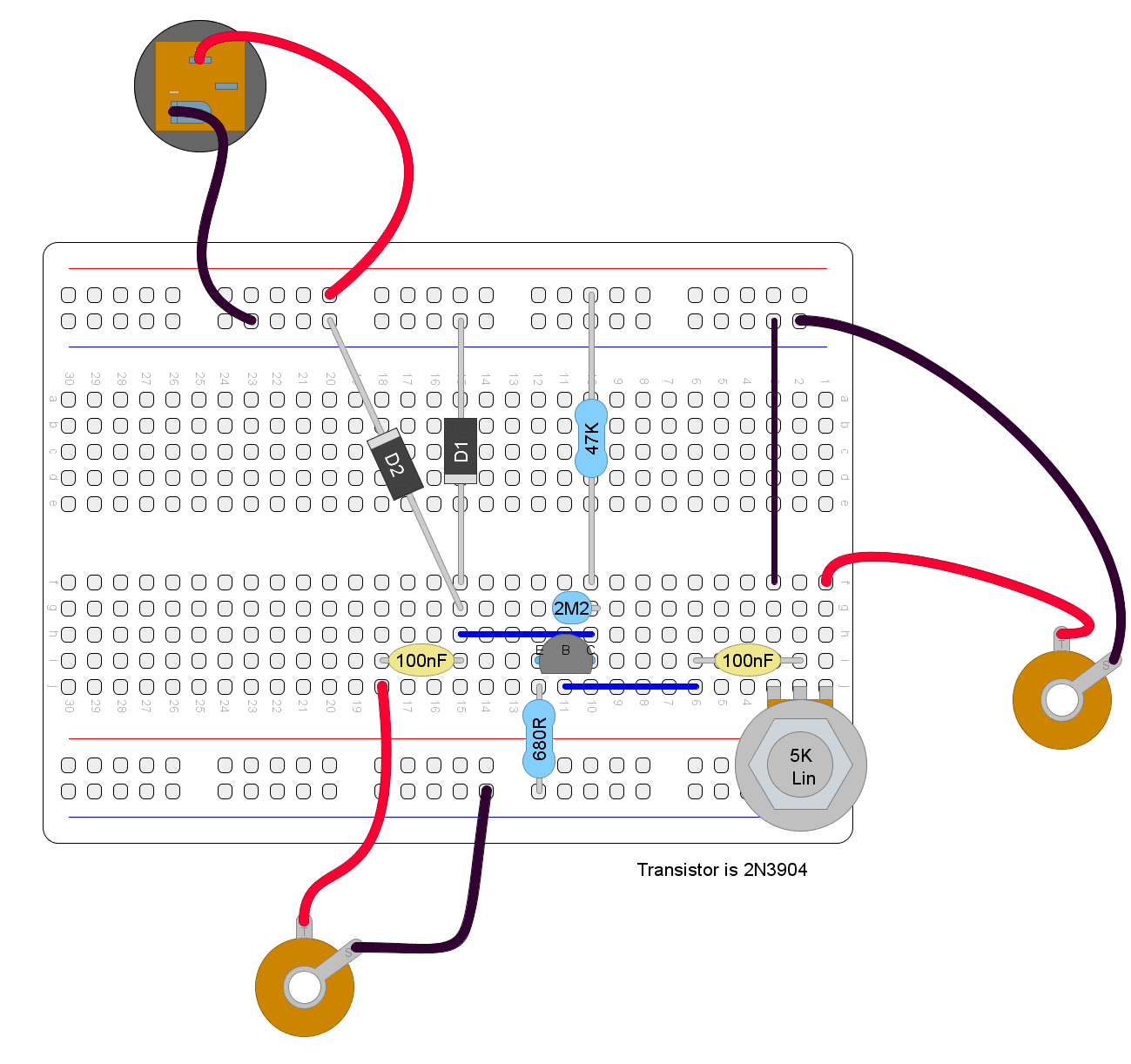
Adding the tone control to the bread board looks like this:
 If you were properly designing a distortion pedal, there are mathematical equations you can use (as well as a bit of trial and error) to work out the best value capacitor and potentiometer to use. For this example, I just used a couple values that would give the most drastic change in tone so that it’s easy to hear and appreciate what’s going on. Feel free to experiment with different values to see what they sound like.
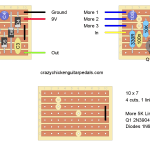
Adding Volume Control To An Electra Distortion Circuit
Finally, let’s add some volume control with another potentiometer. It’s all well and good playing loud, but sometimes (not often, but sometimes) we don’t want to blow everyone’s heads off.
A volume knob is simply a potentiometer acting as a voltage divider. Since volume is just a function of voltage, lowering the voltage output of a pedal will lower the volume.
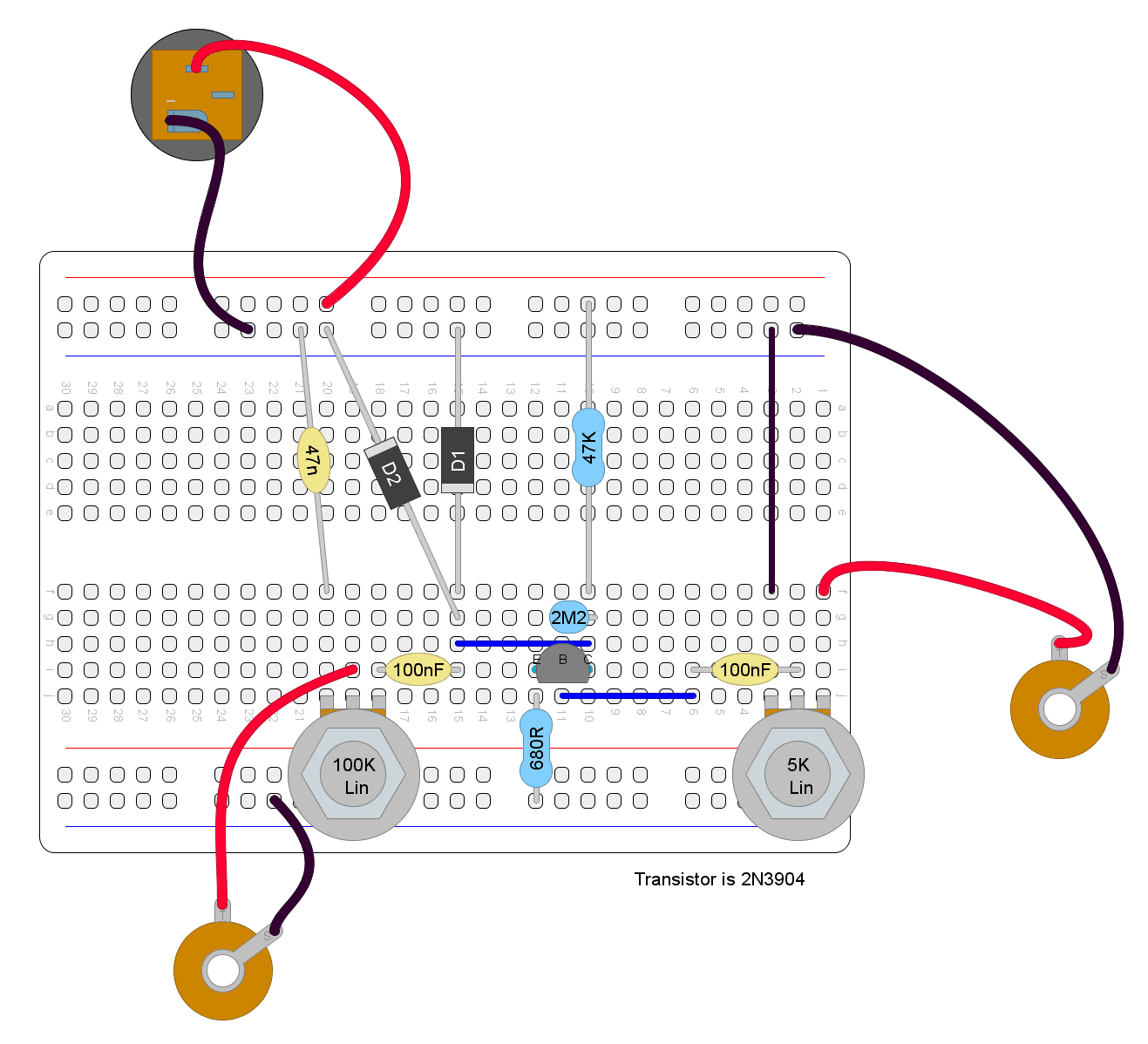
So let’s put a voltage divider pot onto the bread board:
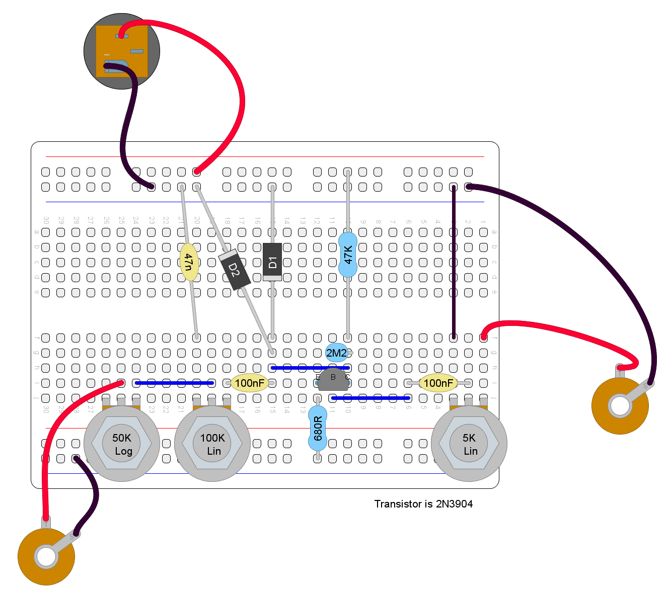
NOTE – the 3rd leg of the volume potentiometer should be going to ground. This is the leg on the left hand side of the 50K log pot (as per the diagram). I’ll update this diagram when I get a chance.
Now you can adjust everything on this pedal, and it’s just as full featured as any store bought distortion pedal out there.
What Will You Do With This Circuit?
The Electra Distortion circuit is simple, but even with its basic components, it sounds great.
If you liked this project and want to take it further, there are lots of things you can do including:
- Really narrow down on the tone control. The values I chose have given from pretty dramatic swings in tone, and probably take too much treble off when going full bass. Try some different values for the capacitor and/or potentiometer to see what happens.
- Change up the transistor. When you remove the diodes, you’re left with a boost pedal that clips just a little bit from the transistor. So obviously the transistor is giving some flavour there as well. Different transistors will have different flavours.
- Play around with the values of the resistors. The resistors are there to control how the transistor is amplifying the signal (and whether the transistor itself starts to clip). Changing up these values will make the transistor behave much differently.
- Change up the diodes. The diodes in the “traditional” Electra distortion circuit are 1N4148, and they’re pretty good all around diodes. See what happens with something different.
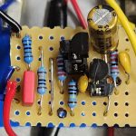
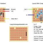
There’s so much you can do with this simple circuit and, if you like what you make, stick it on some stripboard and have your own one of a kind distortion.
Finally, if this has interested you and you want to start soldering something, take a look at my guide on how to make a distortion pedal. The guide is for an EarthQuaker Devices Speaker Cranker that uses the Electra Distortion as a basis. The guide walks you through the equipment and components you’ll need in a step by step fashion.
Let me know what you make.
Related posts:
 How To Make A Distortion Pedal
 Greer Amps Green Giant On Stripboard
 What Is Gain (And How It’s Different From Volume)
 EartherQuaker Devices Speaker Cranker On Stripboard
 Building And Modding A Tube Screamer On A Breadboard
 How To Make A Guitar Pedal Tester And Audio Probe
 Lovepedal Champ On Stripboard
 EarthQuaker Devices Acapulco Gold On Stripboard
 What Is Gain Stacking And How Do You Do It?
 ProCo Rat On Stripboard
“For the purpose of this article, I’ve chosen to simply restrict the signal coming into the circuit. Replacing the 680R resistor with something like a 1K potentiometer would probably work better, but I felt it kind of got in the way of understanding the bread board layout.”
Can you add an example that shows the 1k potentiometer replacing the 680R?
Looks like you found this article already, ignore my other comment! In the short term check out something like the circuit for the ZVEX SHO (https://crazychickenguitarpedals.com/guitar-pedal-blog/guitar-pedal-builds/zvex-super-hard-on-on-stripboard/) which is doing proper gain control. I do want to go deeper on the Electra circuit here and design something custom that’s well balanced and really thought out! So something with that will come (eventually) – just don’t know when yet!