 I’ve touched on this subject a lot, but I want to approach it differently now. Namely, from the perspective of the potentiometer that is controlling the gain in an overdrive, distortion, or fuzz pedal. When talking about this before, I’ve mostly gone through how clipping diodes work in guitar pedals and how they cause clipping depending on where they’re placed in the circuit. Clipping can also happen in transistors when they hit their saturation region. I’ve even written a fair bit on what gain is. That being said, all those links aren’t necessarily background reading; I’m going to try and write this article to be accessible to all, but if you’re more curious on these concepts, check out all that stuff I just linked.
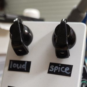
Whether the knob on your guitar pedals says “gain,” “drive,” “distortion,” “fuzz,” or something else, it’s basically doing the same thing: increasing or decreasing the gain of the signal through either an operational amplifier or a transistor. This knob is just a potentiometer that adjusts resistance, and that’s really all you’re doing.
Whether you’re using a distortion, overdrive, or fuzz, the knob is still doing the same thing; it’s just what happens with either the diodes or the transistors itself that creates the clipping (i.e. how dirty the signal sounds and what the quality of that dirt is).
Distortion, overdrive, and fuzz are one of the many things that guitar pedals can be designed to do, and they’re also some of the core effects that people use.
How A Dirty Audio Signal Is Created
I’m going to start at the end here, otherwise people who are unfamiliar with clipping circuits will keep wondering how the signal gets distorted while I talk about how op-amps and transistors make gain.
First, let’s quickly look at how clipping in guitar pedals happens with diodes.
Diodes have some interesting behaviours. They can be used for a lot of things like regulating voltage and rectifiers. In guitar pedals, we usually use them to make distorted noises because it sounds cool. This is called clipping. You can read the whole article on clipping diodes that I linked at the beginning of this article, but the short version is that, when over a certain threshold, diodes cause a voltage drop on an electrical signal. When they cause this drop, the top or bottom of the signal (depending on the orientation of the diode) is “clipped” off. When the signal is a sound signal, it makes it sound distorted (i.e. overdriven, fuzz, or distortion). When an electrical signal comes into a guitar pedal, it’s pretty low in voltage, not enough to trip the diode. That signal is then amplified with an op-amp or a transistor (this is the gain I’ve been talking about) to the point where the diode’s threshold voltage is achieved and it starts clipping the signal. The more you turn that gain, drive, or distortion knob, the higher the voltage goes, so the more of the signal that gets clipped off, causing more distorted sound.
With diode based clipping, the gain control is the same regardless of the effect; either way you’re increasing the electrical signal so that the diodes get cranky. The type of clipping you get (i.e. soft or hard clipping/overdrive or distortion) depends on where the diodes are placed in the circuit, but that’s a bigger topic.

Now, let’s look at how clipping in guitar pedals happens with transistors
Transistor clipping, as an electrical concept, is a bit more complicated than diode clipping, which is kind of ironic because circuits that just use transistor clipping to create fuzz pedals are some of the simplest.
As mentioned, transistors are used to amplify a signal. Adjusting that gain knob affects how much voltage is going to the transistor and therefore how much louder things get. The fun happens when you push the transistor into its saturation region. Here, the delicate balance of the voltage of the signal going into the transistor and the voltage being supplied to it is basically switched around, causing the transistor to amplify the signal, but also not have enough electrons to do a good job of it. This causes the transistor to start behaving like a diode and clip the signal.
How Op-Amps And Transistors Increase Electrical Signals
By now, you’ve probably gathered how gain knobs work in guitar pedals and how adjusting this knob creates more overdrive/distortion/fuzz. Turn the knob, the signal increases, and this makes the (non-adjustable) diodes clip more of that signal because it’s bigger. This is already getting a lot more technical than my article on how a volume knob works, but if you’re satisfied with the explanation so far, you can stop reading here. If you want to better understand the actual placement of things in a circuit, read on.
How Transistors Increase Gain
Again, I’ll go through this briefly, you can read my whole guide to transistors in guitar pedals if you want to get technical.
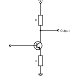
Very broadly, a transistor consists of a base, a collector, and an emitter. The signal comes into the base and, depending on whether it’s a PNP or an NPN transistor, how it works with the collector and emitter is different, but let’s use NPN transistors in this example.
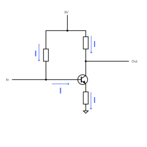
For clean amplification in a transistor, the voltage of the signal going into the base needs to be higher than the emitter voltage, but lower than the collector voltage. This is done by biassing the signal (i.e. giving it a bit of an electrical boost). You can then adjust voltage at the collector by varying the resistance (i.e. turning the gain knob). Changing this resistance changes how much gain there is and what the signal strength is.
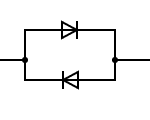
From there, you can pass the signal through some diodes to get clipping.
How Op-Amps Increase Gain
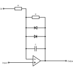
An operational amplifier, or op-amp, is a bit of a complicated device, but it’s basically a bunch of transistors working together to amplify a signal a lot. An op-amp has a feedback loop that creates this gain through a voltage divider.
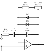
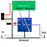
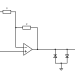
The above shows the feedback loop of an Ibanez Tube Screamer. We can see the op-amp as well as the feedback loop with both a resistor and a potentiometer. Within the feedback loop are two diodes, which create the overdriven sound. The additional capacitors are there to balance tone.
That may not make a lot of sense without much context, but the short explanation is that a voltage divider brings voltage down depending on how the resistors are arranged. Since a potentiometer (i.e. gain knob) is just a variable resistor, you can change up the resistance in the voltage divider section of the op-amp’s feedback loop (labelled P1 in the diagram above), adjusting the gain.
And just like with a transistor, you can then add diodes into the amplified signal’s path to clip it, causing overdrive or distortion.
And That’s How Gain Knobs Work In Guitar Pedals
I know some parts got a bit technical, but hopefully it’s all general enough for a novice to understand how a gain or distortion knob on a guitar pedal works.
The super short summary is that although this knob is usually what you turn to adjust the level of distortion, you’re actually increasing how much the signal is amplified. That amplified signal is then going through diodes, which is what’s actually clipping the signal and causing the change in sound (for diode clipping at least). In transistor clipping, the transistor is both amplifying the signal and acting as a diode, but you’re still doing the same thing with the knob.
If that was of interest to you, feel free to dig deeper into some of the resources I’ve linked to.
Related posts:
 How Do Guitar Pedal (And Guitar) Volume Knobs Work?
 What Is Gain (And How It’s Different From Volume)
 What’s The Difference Between Overdrive, Distortion, And Fuzz?
 What’s The Difference Between Symmetrical And Asymmetrical Clipping?
 How High Pass And Low Pass Filters Work In Guitar Pedals
 How To Wire A Guitar Pedal Foot Switch (3PDT)
 Potentiometer Wiring: How To Wire A Potentiometer
 What Is A Voltage Divider?
 How To Wire Guitar Pedal Enclosures
 How To Use A Distortion Or Overdrive Pedal