Most guitar pedals use a 9 volt direct current. There are pedals out there that use something else, but 9 volts is the most common, especially when it comes to DIY guitar pedals.
However, what do you do if you need something lower than 9 volts? What if your pedal needs both 9 volts and something else, like 4.5 volts? This scenario is actually pretty common; 9 volts isn’t good for everything in a guitar pedal…
And this is where a voltage divider comes in.
All a voltage divider does is lower the voltage of an electrical signal to a desired amount. Then you can use it!
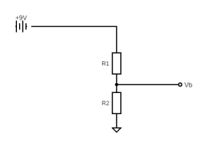
Starting a little bit at the end, the above schematic shows a basic voltage divider. 9 volts goes into R1, lowering the voltage to some value, Vb. You can then use Vb where it’s needed in your pedal.
Let’s explore how this works.
Using Ohm’s Law To Understand Drops In Voltage
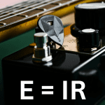
Ohm’s law is a basic electrical equation that explains the relation between voltage, current, and resistance. It states:
Where:
- E = voltage
- I = current
- R = resistance
Take a look at the longer Ohm’s law article linked above for more history on the notation convention here.
The key thing to understand with Ohm’s law is that it’s a relationship between voltage, current, and resistance. It’s also important to note that, in a circuit, the current will remain constant. We can use this to our advantage when calculating the voltage drop across resistors in series.
This makes the most sense when looking at resistors in series.
In series, we can treat all the resistors as one by just adding them up, then use that Ohm’s law to calculate the current. With the current known, we can then use Ohm’s law again to calculate the voltage drop across each resistor.
Here’s an example.
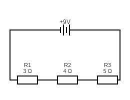
The total resistance in this circuit is 12 (3 + 4 + 5). So we use this in Ohm’s law to find the current.
V = IR
Therefore
I = E/R = 9/12 = 0.75 amps
Remember, the current remains constant. So, by keeping current constant, we can then figure out how much the voltage drops across each resistor.
Let’s take three voltages, V1, V2, and V3. Each corresponds to its respective resistor (R1, R2, and R3).
V1 = IR = 0.75 x 3 = 2.25 volts
V2 = IR = 0.75 x 3 = 3 volts
V3 = IR = 0.75 x 5 = 3.75 volts
And to check your work, add up the three voltage drops to make sure they equal the original voltage (9 volts).
I also have more information on resistors and how they work if you would like to know.
How This Relates To Voltage Dividers
So, we can see how voltage drops across each resistor in series.
In the example below, since the voltage drops by 2.25 volts across R1, the voltage after R1 is 6.75 volts. This means if you take a wire coming off the circuit just after R1, that wire will have 6.75 volts in it.
You can, of course, adjust the levels of each of the resistors to get a specific voltage where needed.
This is even simpler with two resistors in series, which is what you typically see with voltage dividers.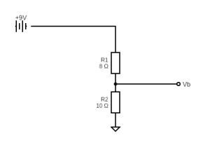
So, in this example, the circuit has a total resistance of 18 ohms (8 + 10).
I = E/R = 9/18 = 0.5 amps
Then you can calculate the voltage drop across each resistor:
V1 = IR = 0.5 x 8 = 4
V2 = IR = 0.5 x 10 = 5
To find out the value of Vb, all you need to do is subtract V1 from the total voltage:
Vb = V – V1 = 9 – 4 = 5 volts
Again, if you want a specific voltage from your voltage divider, modify the values of the resistors.
Voltage Divider Formula
Of course you don’t want to have to go through those steps each time you’re making a different voltage divider, so there’s a handy formula to figure it out quickly.
The formula is:
Voltage Dividers In Guitar Pedals
A common set up in guitar pedals is to make a voltage divider to create 4.5 volts. This works well when biasing an op-amp.
Since 4.5 volts is exactly half of the usual 9 volts used in a guitar pedal, all you need to do is use two resistors of the same amount. The whole thing is a ratio, so using two resistors that are equal just splits the voltage.
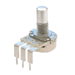
But voltage dividers come up a lot more in guitar pedals, often in volume and gain control. This is usually in the form of a potentiometer.
Without going to deeply into, a potentiometer is essentially two resistors in series. Take a look at my how potentiometers work for more information.
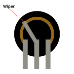
Here’s a potentiometer wired to be a voltage divider:
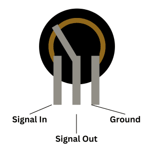
Where “signal out” is just the same as Vb in the example above.
Voltage Dividers In Volume Control
To raise or lower the volume of a guitar signal going through a pedal, all you need to do is raise or lower that signal, and, since it’s an electrical signal, you can use a voltage divider to modify this.
With a potentiometer, a voltage divider (and therefore volume control) looks like this:
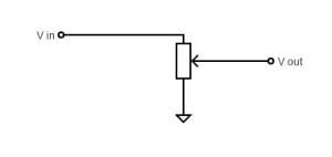
Turning a volume knob “up” decreases the resistance for R1, meaning a lower voltage drop and therefore louder guitar signal. Turning the knob “down” introduces more resistance and makes a quieter guitar.
Voltage Dividers In Gain Control
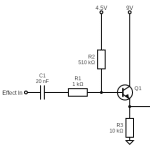
Gain through an operational amplifier is created through a voltage difference between the input voltage and the voltage drop in a feedback loop. There’s a lot more to it than that, but that’s the simple explanation at least! To get that voltage drop, you need a voltage divider.
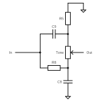
Here’s a basic operational amplifier feedback loop with a voltage divider:
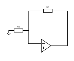
It may be hard to spot if you’re used to seeing voltage dividers in simpler schematics, but R1 and R2 are in series and the wire going back into the op-amp is similar to that of Vb in the earlier schematics.
If you replace R1 with a potentiometer, you can then vary the resistance and therefore the voltage drop. This modifies that gain!
That’s Voltage Dividers
Understanding voltage dividers, how they work, and where they commonly appear in guitar pedals can be useful in better understanding pedal schematics. And if you understand schematics, you can make better and cooler modifications.
Have fun.
Related posts:
 How High Pass And Low Pass Filters Work In Guitar Pedals
 How Do Guitar Pedal (And Guitar) Volume Knobs Work?
 Ohm’s Law: Explanation And Applications
 Ultimate Guide To Resistors In Guitar Pedals: What They Do And How They Work
 Understanding Mid-Scoops And The Big Muff Tone Circuit
 Ultimate Guide To Diodes In Guitar Pedals: What They Do And How They Work
 Ultimate Guide To Potentiometers In Guitar Pedals: What They Do And How They Work
 Ultimate Guide To Transistors In Guitar Pedals: What They Do And How They Work
 Potentiometer Wiring: How To Wire A Potentiometer
 How To Read A Circuit Diagram