If you look at any schematic for a guitar pedal, you’ll see high and low pass filters throughout the circuitry. Sometimes they’re not so obvious, but once you learn how to spot them you’ll see them everywhere!
High and low pass filters, sometimes called low cut and high cut filters, are used to shape the guitar’s tone as it moves through the pedal. Some pedals only do tone shaping, while many others, whether it’s an overdrive pedal or a chorus pedal, will take the opportunity to shape tone with high and low pass filters so it better suits the sounds that are being made by the pedal. Sometimes these filters can be adjusted by the user through a potentiometer, sometimes they’re hard wired in.
If you’ve already read my guide to resisters in guitar pedals, you will already know the set up of these filters, but I didn’t go into much explanation of what’s going on. Nor did I explain how to use the formula to calculate cutoff frequency. I just put it there. This was the same for my guide to capacitors in guitar pedals.
If you haven’t read those guides, I suggest you do. I’m not really assuming any knowledge in this article, but getting a general background of what these two components do in guitar pedals will give you a solid grounding.
What Are High And Low Pass Filters?
As mention, high pass filters are sometimes called low cut filters. On the other side of things, low pass filters are sometimes called high cut filters.
As the names would suggest, a high pass filter lets high frequencies through while cutting the low ones. Meanwhile, a low pass filter lets low frequencies through while cutting the high ones.
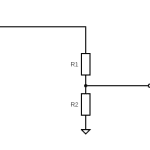
Both these filters look very similar, just the opposite way around:
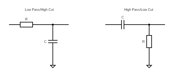
As you can see, the low pass filter has a resistor and then a capacitor going to ground. A high pass filter is the opposite with a capacitor and then a resistor going to ground.
Let’s look at how these work.
How High And Low Pass Filters Work
When I first learned about high and low pass filters, I just took it as given that that was what they did. You’re welcome to as well, but if you want to know the actual electrical bits behind it, it’s not overly complicated to understand how high and low pass filters work. This is knowledge that works for guitar pedals and electronics in general.
First, let’s look at the maths behind high and low pass filters. To understand the final formula, we have to work our way backward a little bit…
First, let’s look at what the reactance (basically resistance in this case) in a circuit for different frequencies:
So you vary the resistance, and the frequency is affected.
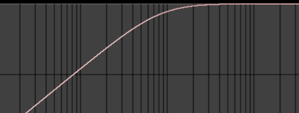
Keep in mind that cutoff frequency isn’t a sudden drop, instead it’s a gradual decline like this:
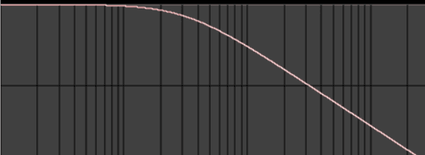
Since it’s a gradual decline, the cutoff frequency is the frequency where only 70% of its initial amplitude remains, and frequencies beyond it are further diminished.

How A Low Pass Filter Works
A low pass filter is has the resistor first and then the capacitor going to ground, like this:
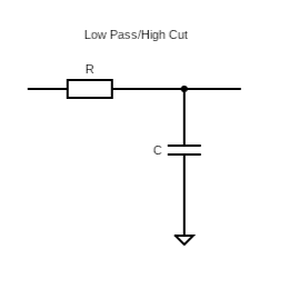
Here you can think that the resistor isn’t allowing the capacitor to charge enough. For lower frequencies, this is fine, but as higher frequencies come through as the capacitor charges, as we know, the effective resistance goes up, stopping these higher frequencies. This gives us a cutoff graph that looks like this:
How A High Pass Filter Works
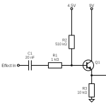
On the other end, with a high pass filter, which has the components the other way around, looks like this:
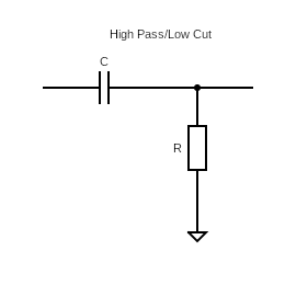
With little to no resistance, the capacitor is naturally blocking lower frequencies (because at lower frequencies, we have a very high reactance). The resistor is acting as a pulldown resistor for anything that sneaks through.
The cutoff graph looks the opposite:
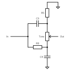
Use This To Shape The Tone In Your Pedals
Now that you know how these work, you can shape the tone in DIY guitar pedals or modding professionally built pedals. A few ideas:
- High/Low pass filters are often put strategically in pedals to shape the tone. Vary the resistance in these static filters to see what happens.
- Turn a high pass filter into a low pass filter and vice versa. This could make things sound too muddy or too thin, but it could work for you.
- Turn the tone potentiometer from high to low pass or vice versa. Again, this could create too much mud or twang, but since it’s variable, you may find a sweet spot.
- Add another filter. If, for example, you generally like a peddle but feels it’s too dark, throw a low pass filter in there to see what happens.
Filtering tone in guitar pedals is one of the many ways to get a unique sound for that pedal, and a great way to start modifying standard and famous designs. Let’s see what you come up with.
Related posts:
 Understanding Mid-Scoops And The Big Muff Tone Circuit
 What Is A Voltage Divider?
 How Do Guitar Pedal (And Guitar) Volume Knobs Work?
 How Does A Drive, Gain, Or Distortion Knob Work?
 Ohm’s Law: Explanation And Applications
 Ultimate Guide To Resistors In Guitar Pedals: What They Do And How They Work
 How To Read A Circuit Diagram
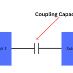 What Are Coupling Capacitors?
 Ultimate Guide To Capacitors In Guitar Pedals: What They Do And How They Work
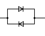 What’s The Difference Between Symmetrical And Asymmetrical Clipping?