In guitar pedals and electronics in general, coupling capacitors are important to keep different parts of a circuit separate and to prevent DC power and other noise from moving from one sub-circuit to another. All in all, it’s quite simple, and that’s really the explanation… but if you want to know more, read on for some examples and applications.
Why Coupling Capacitors Work And Why Use Them
If you read my guide to capacitors, you’ll note that DC current can’t flow through a capacitor. Because of this, by simply placing a capacitor between two circuits where you don’t want DC current to pass through, you can allow AC current through while stopping the DC.
This is particularly useful in guitar pedals because we use DC power to get our effects going! In a guitar pedal (and other electronics), we want our signal to come through the way we want it to come through, not with the added noise of DC. This poses a problem, because we also need that DC to power our circuits. That’s why we throw a coupling capacitor in. It allows us to use DC power while also not having it mess up our signal.
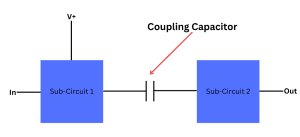
Because of this, you’ll often see coupling capacitors used either between sub-circuits of a larger guitar pedal circuit, or at the very end of a guitar pedal circuit before the signal goes to the output.
Examples Of Coupling Capacitors In Guitar Pedals
As mentioned, coupling capacitors are usually put between different sections of a guitar pedal circuit or at the end so that the DC signal doesn’t pass through and add undesirable noise to our signal.
If you take a look at a really simple circuit like the ZVEX Super Hard On, you’ll see two coupling capacitors: C1 and C3.
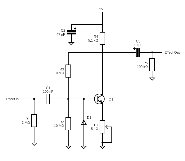
We can see that the 9V DC power supply comes in, and we only want that to power the transistor (Q1). Those two coupling capacitors at C1 and C3 keep that DC power supply confined to that small part of the circuit. It’s like a little jail for DC.
In a more complex pedal circuit, like on the schematic of an Ibanez Tube Screamer, you’ll see plenty of coupling capacitors. On the schematic below the coupling capacitors are C1, C2, C7, C8, and C9. Feel free to click on the image to enlarge it to see better.
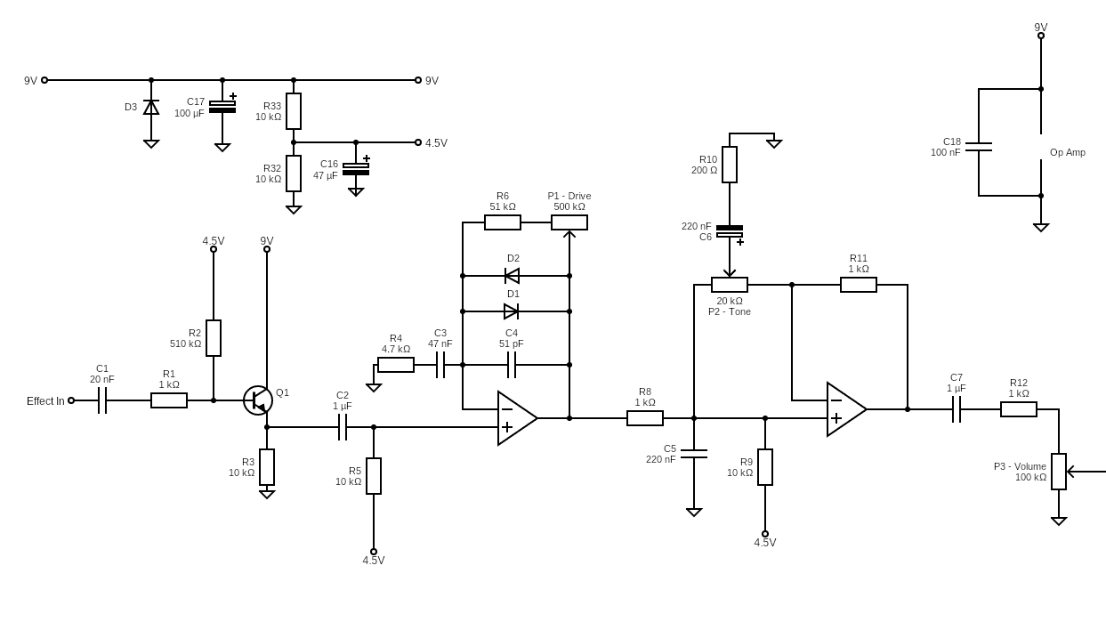
Let’s look closer at this and understand why so many coupling capacitors are needed:
- C1 and C9: these are kind of obvious and are the input and output coupling capacitors that are seen in simpler circuits.
- C2: this is really interesting. Between C1 and C2 is a circuit for the input buffer of the pedal. This amplifies the signal somewhat and also biases the current to 4.5 volts. Although the op-amp after this part of the circuit is also powered with DC, we don’t want the noise from the first use of DC to come through. We also don’t want the DC current going into the non-inverting input of the op-amp.
- C7: after passing through the two amplification stages of the circuit, for similar reasons to before, we want to stop the DC from coming through to the next section of the circuit. It’s all about isolating the different uses of DC in the sub-circuits of the larger circuit.
- C8: C8 is working with C9 to once again isolate a section of the circuit, in this case the output buffer. Obviously we don’t want the DC signal going to the output, which is why C9 is there. C8 is helping to keep it isolated to just the output buffer. I haven’t done a full analysis of this, but I imagine C8 is fairly inconsequential and may also be doing a little bit of tone balancing in conjunction with the volume potentiometer. That’s just a theory though.
So all of that has just been a long way of saying that it’s not just about input and output, it’s also about isolating different parts of a circuit.
Related posts:
 What Are Decoupling Capacitors?
 Ultimate Guide To Resistors In Guitar Pedals: What They Do And How They Work
 Ultimate Guide To Capacitors In Guitar Pedals: What They Do And How They Work
 Ultimate Guide To Diodes In Guitar Pedals: What They Do And How They Work
 Ultimate Guide To Transistors In Guitar Pedals: What They Do And How They Work
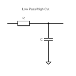 How High Pass And Low Pass Filters Work In Guitar Pedals
 What Is Transistor hFE?
The Difference Between Silicon And Germanium Transistors
What Is Transistor hFE?
The Difference Between Silicon And Germanium Transistors
 The Difference Between NPN And PNP Transistors
 How To Wire Guitar Pedal Enclosures