A quick note on terminology: a potentiometer has three pins, often numbered 1, 2, and 3. Throughout this article I’ve tried to simplify it by referring to left and right pins, and it’s seemed to confuse a couple people. Whenever anyone talks about potentiometer pins, they’re looking at it face on with the arm pointing upwards. This makes it so the pin on the left is pin number 3, the pin in the middle is pin 2, and the pin on the right is pin 3.
What Is A Potentiometer?
Firstly, if you haven’t read my guide to resistors in guitar pedals, I highly suggest you go ahead and read it first before learning about potentiometers in guitar pedals. This is because a potentiometer is essentially just a variable resistor. If you understand what resistors do in guitar pedals, you’ll largely understand what potentiometers (or pots) do in guitar pedals.
So what is a potentiometer? As already mentioned, a pot is just a variable resistor. By turning the dial on a potentiometer, you’re simply varying the resistance between its pins.
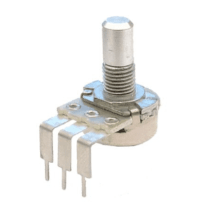
A potentiometer looks like this:
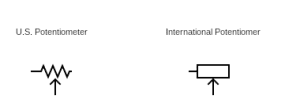
And the schematic of a pot looks like this (with the U.S. version on the left and the international version on the right).
You’ll notice that there are three pins to a potentiometer, and obviously each pin does something different. Understanding what happens with each pin is pretty simple from the schematic. Here’s a schematic where there’s an input from a voltage on the first pin, an output to “somewhere” on the middle pin, and an output to ground on the third pin.
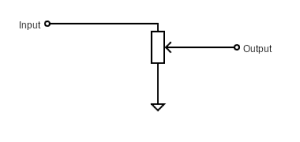
Very often there’s no need to use the third pin (more on this later). For a situation like this, it’s acceptable to simply not wire the third pin or just wire it back to the second pin. This is represented in schematic as one of these:

How Does A Potentiometer Work?
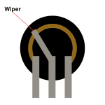
Assuming you’ve used a guitar pedal before, you’ve probably used a potentiometer. If you look inside a potentiometer, you’ll see the two outer pins connected by a resistant surface; the wiper, which is connected to the middle pin, adjusts the resistance between the wiper itself and the pins. So, the more to the right the wiper is, the more resistance there is between the wiper and the left (first) pin, and vice versa.
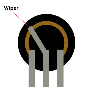
And that’s pretty much how a potentiometer works. Depending on what you’re using the pot for, you may just want to adjust a single bit of resistance. If you’re creating something like a voltage divider, adjusting the resistance between both pins is what you need. I’ll go through these applications in more detail later on.
Of course there are different kinds of potentiometers; they don’t all simply work as a dial. Some work as a slider, but it’s essentially the same thing, just straightened out.
If you’re curious about how the pins in a pot correspond to the wiring, I have an article all about potentiometer wiring you may want to read.
Types Of Potentiometers Used In Guitar Pedals
As mentioned, there are a few types of potentiometers. You’ll mostly come across rotary pots when making guitar pedals, but other types are not unheard of.
Rotary Potentiometers
As mentioned, these are likely the pots you’re most familiar with. These just work like a dial or a knob.

On guitar pedals, these are used to adjust all sorts of settings, from your basic gain, tone, and volume, to the more exotic settings given in stranger pedals.
Slide Potentiometer
These are less common in guitar pedals, but they do pop up from time to time.
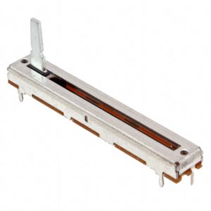
These pots just have a slider instead of a wiper to change the resistance between the two ends. These can be a good look on a guitar pedal, but they’re usually more at home on things like mixing boards.
Trimmer/Trim Pot
A trimmer potentiometer is smaller than the rotary pots you’ve already seen, but it basically works the same way.
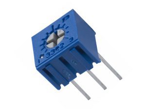
The big difference is that they’re not built to be easily interacted with. Instead, the resistance in a trim pot by turning the dial using a screwdriver. These pots are usually used when you want to make a semi-permanent adjustment, but don’t want the user to be able to do it. They’re not used as much in guitar pedals.
Linear Versus Logarithmic Potentiometers
You may have seen information about linear and logarithmic potentiometers. The big difference here is that on a linear potentiometer, the resistance change is equal as you move the wiper. With a logarithmic pot, the resistance change increases in larger amounts the more you rotate the knob, so it goes from a small change in resistance to a large change very quickly.
There’s no “right” type of pot to use in DIY guitar pedals, but I’ll make suggestions when we go through applications.
Enjoying This Component Guide?
Learn more about potentiometers and other guitar pedal components.
How Are Potentiometers Measured?
Like resistors, potentiometers are measured in ohms. The measurement is simply the largest resistance you can get out of the potentiometer.
This value is usually written on the pot. It’s hard to miss!
The larger the value of the pot, the larger resistance it can give. While you may be tempted to go with a big number to get more variability, that’s not always a good thing. I’ll go through typical values in applications.
The only other thing to be aware of is that potentiometers can be logarithmic, linear, or inverted logarithmic, so you’ll see a marking on the pot to indicate its type:
- A – logarithmic
- B – linear
- C – inverted logarithmic
- W – W taper
- this pot is logarithmic for the first half of the rotation then reverse logarithmic for the second half.
- G – G taper
- The opposite of W taper. It’s reverse log for the first half then log for the second.
I’ve had a lot of trouble finding and sourcing W and G taper potentiometers. I’ve seen them online in places but not in the values I’m after. If you’re trying to clone a circuit for your own DIY guitar pedal and can’t find W/G taper pots, a linear potentiometer is the best substitute as it’s (very) approximately the same change in resistance.
Logarithmic pots are sometimes called audio potentiometers, so just remember A for audio and you should be fine.
What Do Potentiometers Do In A Guitar Pedal?
I already mentioned that you should read my guide to resistors in guitar pedals before reading this guide. If you have, great! You probably already have an idea of what potentiometers can do in guitar pedals, but I’ll go into a little more depth here.
Voltage Dividers – Guitar Pedal Volume Adjustment
A voltage divider is created by putting two resistors in series and having an output between them. The theory behind this is explained in my resistor article and my explanation on Ohm’s Law (see, should have read it).
Since the output voltage is dependent on the difference in value between the two resistors in series, this can be adjusted using a potentiometer. The output voltage is coming out of the middle pin while resistor one is the left (first) pin and resistor two is the right (third) pin. A voltage divider made from a potentiometer looks like this on a schematic:
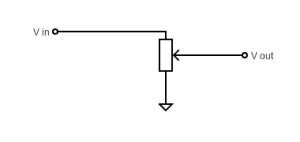
To wire this, place the positive wire into the left (first) pin of the pot, your output voltage wire into the middle pin, and the ground wire into the right pin.
This is basically the set up of a volume knob on a guitar pedal, an amp, or a guitar. The volume of the sound is simply the amount of voltage that’s allowed to flow, lowering that voltage through a voltage divider lowers the volume, raising the voltage raises the volume. Easy!
Low Pass And High Pass Filters – Guitar Pedal Tone Adjustment
A resistor-capacitor (RC) filter, also known as a high pass/low cut filter or a low pass/high cut filter depending on the arrangement, is a way of shaping the tone of a guitar signal. An RC filter works by placing a resistor and capacitor in series, and sending the cut signal to ground.
The equation for the cutoff frequency is:
Where R is resistance and C is capacitance.
So, if you adjust the resistance, you can adjust the cutoff frequency and therefore the tone of the guitar signal. And obviously you adjust the resistance using a potentiometer!
The schematic for a RC filter looks like this:
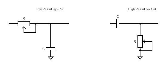
If the resistor is put before the capacitor, you have a low pass filter. If the resistor is put after the resistor, you have a high pass filter.
Adding Gain Through An Op-Amp Or Transistor
The gain achieved from an op-amp is, once again, increased and decreased by adjusting the resistance in the feedback loop.
So, once again, you can easily adjust the resistance in the feedback loop, and therefore the gain, with a potentiometer. It looks like this in a schematic, all you need to do is place a pot in place of R1:
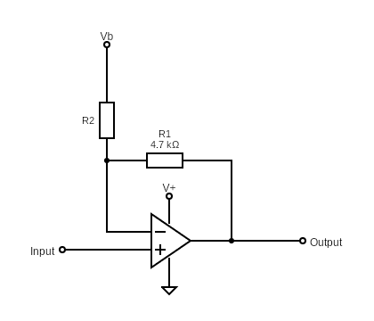
The wiring of this is quite simple, since you’re only actually using two pins. So you can wire this with the input going to the left pin and the output coming from the middle pin. You can also wire the right pin to the middle pin if you like.
And Many Other Uses
Depending on the type of guitar pedal you’re making, you’ll likely be using a potentiometer in a different scenario to adjust levels. This may be adjusting the echo effect in a reverb pedal, or some setting with a weird name in a more unique pedal. Ultimately this is all down with a potentiometer varying the amount of resistance. Generally speaking, this resistance variance will be used to adjust voltage, gain, or tone, just in a different configuration than the “vanilla” versions above.
What Potentiometers To Use In Guitar Pedals
Ultimately, the type of pot to use and its value is up to you and what kind of DIY guitar pedal you’re building, but there are some guidelines.
Volume adjustment is generally done with a logarithmic pot. Why? Because that’s how the decibel rating is scaled, and that’s because human hearing is logarithmic as well. We don’t hear volume increases in a straight and linear fashion; instead we hear small changes first, then perceive differences in big changes as volume gets louder. Using a logarithmic potentiometer for volume is more natural to the ear.
For tone control, linear potentiometers can come in handy for tone control because you want basic equal changes in order to fine tune between tones, not a sudden jump in tone as you adjust the pot upwards.
Gain control can use either linear or logarithmic potentiometers, depending on what you want. Again, a linear pot can give you some good fine tuning across the entire range. However, if you’re trying to design a guitar pedal with some serious crunch on higher levels, but more finesse on lower levels, a logarithmic pot may give you that variable control.
Summing Up
Potentiometers act as variable resistors in guitar pedals. With them, you can create volume adjustment knobs, tone adjustment knobs, and gain adjustment knobs. Beyond that, they can be used to adjust the resistance for more complex guitar pedals to change settings as needed.
If you know how resistors work in guitar pedals, you already know how pots work, but they add a whole other level to guitar pedal building! Sure, you can make a guitar pedal that just makes one sound, but with pots you can adjust that sound. I thought this article would be a lot short because I’d basically be writing about resistors, but it actually got quite long! And that’s how useful pots are.
Related posts:
 Potentiometer Wiring: How To Wire A Potentiometer
 A Versus B Potentiometers (And When To Use Them)
 How Do Guitar Pedal (And Guitar) Volume Knobs Work?
 How Does A Drive, Gain, Or Distortion Knob Work?
 How To Wire A Guitar Pedal DC Power Jack
 The Difference Between SPDT, DPDT, And 3PDT Switches And How To Use Them
 The Difference Between Silicon And Germanium Transistors
 What Are Coupling Capacitors?
 The Difference Between NPN And PNP Transistors
 What Are Decoupling Capacitors?
