A quick note on terminology: a potentiometer has three pins, often numbered 1, 2, and 3. Throughout this article I’ve tried to simplify it by referring to left and right pins, and it’s seemed to confuse a couple people. Whenever anyone talks about potentiometer pins, they’re looking at it face on with the arm pointing upwards. This makes it so the pin on the left is pin number 3, the pin in the middle is pin 2, and the pin on the right is pin 3.
Potentiometers are an electronics component that are essentially used as variable resistors in guitar pedals and other electronics. I have an article on how potentiometers work and the different types if you want more information, but if you’re already pretty familiar with potentiometers but need information on how to wire them, you’re in the right place.
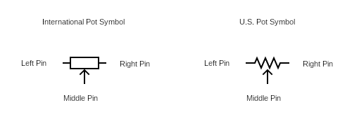
As mentioned, potentiometers work as variable resistors. A typical potentiometer has three pins, and how things are wired to these pins will depend on how they behave.
Potentiometer Wiring And Potentiometer Pins
Typically, potentiometers have three pins. There are dual gang pots out there, which have six pins, but I won’t be covering that here. This article is about the typical wiring of potentiometers, especially for guitar pedals, and less about unusual potentiometer wiring practices.
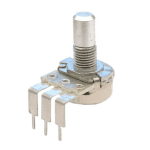
Here’s what the inside of a potentiometer looks like:
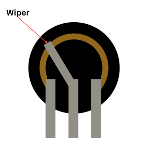
When you turn the dial on a potentiometer (or adjust the slider in a slide pot), you adjust the resistance between the resistance between a given pin and the wiper itself.
Because of this, a potentiometer is usually wired to have a signal or current through one of the outer pins then out through the middle pin. The other outer pin can be unused or go to ground depending on what the pot is doing.
I’ll go through some typical uses/wirings for potentiometers, but if you’re unsure how to convert a wiring diagram to how it’s wired on a physical component, it’s actually quite easy.
Volume And Dimmer Potentiometer Wiring
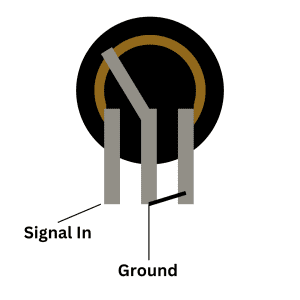
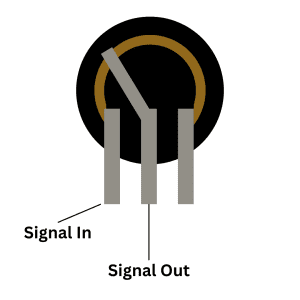
When wiring a potentiometer to reduce a signal, like for volume control, the signal or current needs to come in then out again. Since the wiper adjusts the resistance between itself and one of the outer pins, that’s the way it’s wired. Here’s that with the pins labeled.
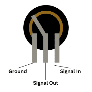
You can see here that the signal comes into the third (right) pin and out of the second (middle) pin. This is because it creates a situation where there is less resistance when the pot is turned fully to the right, which makes the volume louder. When the potentiometer is turned completely to the left, there’s more resistance therefore less volume. All of this makes is so that turning “up” the volume is a clockwise turn which is how you want it.
With this wiring, the potentiometer is acting as a voltage divider, which has a wiring diagram like this:
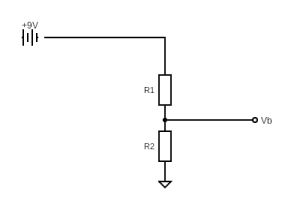
In the diagram above, R1 is the resistance between the left/first pin and the middle/second pin, the line to Vb is the middle pin, and R2 is the resistance between the middle pin and the right pin.
Tone Control Potentiometer Wiring
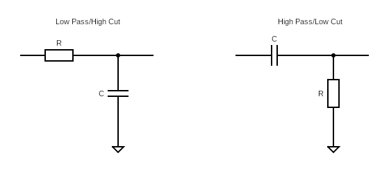
A potentiometer can be wired to be used for some forms of tone control, creating a low or high pass filter.
For a high or a low pass filter, the middle pin is sent to ground. The third pin is either not used or wired to the middle pin (it’s the same electronically).
A low pass filter and high pass filter is diagramed like this:
Creating a low pass filter with a pot, the wiring diagram looks like this:
With a potentiometer, the diagram is like this:
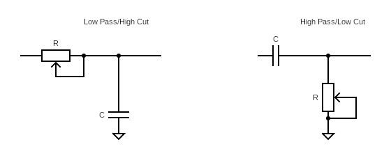
To wire the actual potentiometer pins for this diagram, here’s how:
Here, you can see that the middle pin and the right pin are wired together. It’s also acceptable to just leave the right pin unwired.
I have a longer article on the explanation of how low and high pass filters work, but the long and the short of it is that by adjusting the resistance, you change what frequencies are being sent to ground. Since the wiper adjusts the resistance between itself and one of the outer pins, you can adjust how much resistance there is and therefore what frequencies are being filtered.
Gain Control And Potentiometer Wiring
Another common potentiometer use is to control gain/distortion in overdrive and distortion pedals. The amount of gain present is controlled by how much voltage is allowed to flow through the feedback loop of an op-amp. Obviously there’s more to it than that, but that’s the basics!
Typically, gain control is wired in a similar way to tone control, under the same principle, but also kind of like a volume control though, just with no ground.
Like with tone control, the right pin can be wired to the middle pin, or just left bare.
Related posts:
 How Do Guitar Pedal (And Guitar) Volume Knobs Work?
 How Does A Drive, Gain, Or Distortion Knob Work?
 Ultimate Guide To Potentiometers In Guitar Pedals: What They Do And How They Work
 How To Wire A Guitar Pedal Foot Switch (3PDT)
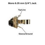 How To Wire 6.35mm (1/4″) Socket
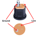 How To Wire A Guitar Pedal DC Power Jack
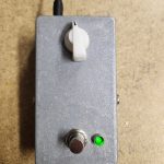
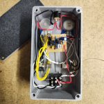 How To Wire Guitar Pedal Enclosures
 A Versus B Potentiometers (And When To Use Them)
 What Do Guitar Pedals Do?
 The Difference Between Silicon And Germanium Transistors
This needs a small edit in the first paragraph.
Currently, pin 3 is called out twice:
“Whenever anyone talks about potentiometer pins, they’re looking at it face on with the arm pointing upwards. This makes it so the pin on the left is pin number 3, the pin in the middle is pin 2, and the pin on the right is pin 3.”
Should read:
“”Whenever anyone talks about potentiometer pins, they’re looking at it face on with the arm/knob pointing upwards. This makes it so the pin on the left is pin number 1, the pin in the middle is pin 2, and the pin on the right is pin 3.” (as per https://beavisaudio.com/techpages/pots/)