The typical foot switch for a guitar pedal, the 3PDT, is a component that goes into pretty much every single guitar pedal. It’s needed to turn the guitar pedal off an on. Well, in actual fact, it’s needed to swap the signal from bypassing the pedal’s circuit to going through the guitar pedal’s circuit. It can be a little bit daunting, and it can be difficult to understand how/why a 3PDT is wired the way it is for a guitar pedal, but once you get your head around it, it’s quite simple.
In this article, I’ll go into a bit of theory on how a 3PDT/guitar pedal foot switch works so that you can understand exactly what you’re doing, then go into a bit more depth on how to actually wire a guitar pedal foot switch for true bypass. If you’re impatient or don’t care, feel free to skip ahead for the exact wiring.
Skip to how to wire a guitar pedal foot switch.
What Is A 3PDT And How Does It Work?
A 3PDT, commonly just called a foot switch, is short for Three Pole Double Throw. This is basically just a triple version of a SPDT; a Single Pole Double Throw.
Let’s start with the SPDT to understand what a 3PDT is and how it works.
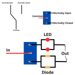
As the name (kind of) suggest, an SPDT gets a single input and can switch between one of two states. This is how your basic light switch works, on or off. A light switch is an SPDT. But an SPDT doesn’t need to only work for completely “on” or completely “off.”
An example of an SPDT that isn’t just on or off would be a switch in a guitar pedal that goes between, for example, LED clipping and silicone diode clipping.

So now let’s look at a 3PDT. It looks like like three SPDT put together, because it essentially is.

An important note: the correct orientation of a 3PDT is so that all the lugs are horizontal. It won’t work if you have it the wrong way around!
So each column of a 3PDT is its own SPDT, and they all work independently of each other. It’s important to understand that each SPDT within the 3PDT is its own switch. They don’t “talk” to each other. All that’s special about the 3PDT is that flicking the switch (i.e. pushing it) throws all three switches at one.

I’ll say it again. Each SPDT within the 3PDT is its own switch. If you can understand this, you can probably start to understand how the signal moves across the switch.
So, when the the foot switch is clicked, you have all of the middle rows being an input/output to the its own SPDT and either the top row or the bottom row active.

Wiring A Very Basic Bypass
Before I launch into the more “complete” bypass for a 3PDT guitar pedal foot switch, let’s look at a very basic bypass on a 3PDT.
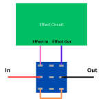
Let’s take a look at a super simple bypass situation.

As with an SPDT, the input signal comes into the middle lug.
I haven’t included the 9V or ground here, but the input and output jacks would have ground and the effect circuit would have a 9V in and a ground.
The bottom lugs in this simple scenario are just a bypass, flipping the switch into this position makes all bottom lugs active, and the signal goes straight across.
Flipping the switch to the upper lugs puts the signal through the effect circuit then out again to the third column and then the output jack.
Again, all three columns are independent of each other. No signal is going from column to column. This is why we need the bypass connection on the bottom lugs and why the signal goes through the effect circuit when switched that way. It’s also why we don’t need anything in the middle column.
This is all basic, but it’s important to understand so that you can understand how to wire a guitar pedal foot switch for power.
Wiring A 3PDT (Guitar Pedal Foot Switch) For True Bypass And Power
There’s more than a few ways to wire up a guitar pedal foot switch/3PDT, but the following is what I like. This is a true bypass wiring for a guitar pedal foot switch and works well with wiring the entire pedal enclosure.
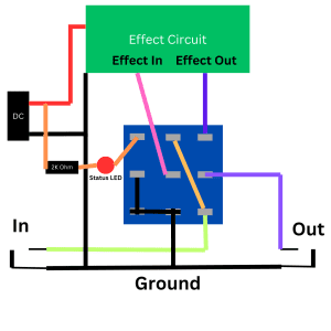
There’s a bit to unpack here, so let’s take a thorough look.
Column Three
This is your basic true bypass, although it may be hard to see. When the footswitch is switch to the down position (row 3), the signal comes in through the input on the bottom lug of column 3 then out through the output of the middle lug of column 3. Everything else is grounded so there’s not much going on there!
Column Two
First, we can see that column three, row three (the guitar signal’s input) is connected directly to column two row one. In the down position, this isn’t doing anything because the signal has nowhere to go, but in the up position the signal can then flow out of the middle lug of column two; this goes into the effect circuit, out through the output, and into column three, row three. Once again out through the middle lug of column three.
Column One
This is basically just handling your status LED. In the down position, the status LED isn’t connected to ground, so it won’t turn on.
In the up position, the status LED is connected to ground via the middle lug, so it lights up. Just don’t forget the 2K ohm resistor in there, otherwise you’ll burn out your LED. You can actually go a lot higher on this resistor, the LED will just be dimmer.
Other than that, it’s actually independent of everything else.
Other Wires
The only other wires to talk about are the 9V wire and the ground coming out of the effect circuit. Obviously the effect circuit needs power, but this is all independent of the switch itself. Ground is common so it’s just doing usual ground stuff.
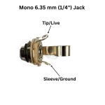
If you’re stuck on how to wire the input and output sockets, here’s how to wire a 6.35 mm (1/4″) jack.
Putting It All Together
Really the only difference between this switch and the simple bypass is the addition of the status LED, but you need the ground in there for everything to work, so a few things get shifted. But in essence it’s the still the same.
I’ve seen variations of this wiring with a slightly different ground configuration, but this one works for me, it’s relatively easy to wire/solder, and it feels reliable, so it’s what I go with.

Other 3PDT Guitar Foot Switch Wiring
This is in no way the only guitar switch wiring out there, but it’s the one that I use. There are, of course alternative wirings that can incorporate a battery but, after learning more and more about it, I’ve decided on two things:
- I’m never going to make a pedal that takes a battery, so I’m not going to learn the wiring.
- Even if I knew it, I wouldn’t share it.
Why is that? A 9V Boss style power supply is cheap and batteries are wasteful. We need batteries for a variety of things, but we don’t need them for guitar pedals. It’s also simpler to wire a guitar pedal foot switch to not need a wasteful battery, so why bother?
But anyway, there you go. That’s how you wire up a guitar foot switch.
Related posts:
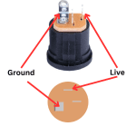 How To Wire A Guitar Pedal DC Power Jack
 How To Wire 6.35mm (1/4″) Socket
 How Do Guitar Pedal (And Guitar) Volume Knobs Work?
 How Does A Drive, Gain, Or Distortion Knob Work?
 What Is Stripboard And How Do You Read Layouts?
 How To Wire Guitar Pedal Enclosures
 What Is True Bypass In Guitar Pedals?
Is It Expensive To Make Your Own Guitar Pedals?
What Is True Bypass In Guitar Pedals?
Is It Expensive To Make Your Own Guitar Pedals?
 The Difference Between SPDT, DPDT, And 3PDT Switches And How To Use Them
 What Do Guitar Pedals Do?