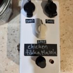
Although it’s important to correctly place and solder in every guitar pedal component, at the end of any pedal build, perhaps the most important thing to get right is wiring the power supply. Sure, there are passive pedals out there that don’t require a power supply, but most of what you’re building is going to need electricity. If you wire your DC input wrong, nothings going to work. This is also usually the case when wiring your foot switch, but I’d argue power is more important.
For most guitar pedals out there, both professional and DIY, you’ll be using a 9 volt 2.1 mm jack that’s wired to be centre negative. This is considered relatively standard for guitar pedals, although often unusual in other electronics, which tend to be wired centre positive.
If the above paragraph makes no sense to you, what I’m referring to is the centre pin of the jack, check it out:
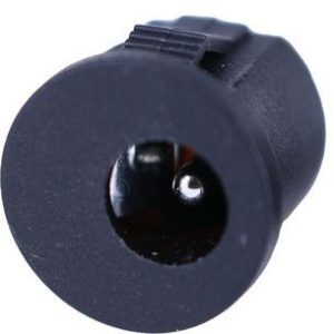
That pin that you can see is wired to the negative/ground. The outer jacket of the plug (the inside of the jack) is the live connection. Centre positive is used pretty much everywhere else because it means the live part of the plug isn’t exposed when it’s not plugged in; that’s safer and more sensible. But the guitar pedal power paradigm is different.’
I’ll go into a tiny bit of history to explain why guitar pedals usually use a centre negative power jack then go into how to wire them. If you have no interest in the history/explanation, you can jump ahead.
Jump ahead to pedal power supply wiring.
Why Guitar Pedals Use A Centre Negative Jack
Although the centre negative standard confuses people sometimes, there is a reasoning behind it.
Back when guitar pedals were first being developed in the 1960’s, they only used batteries. Look at an old Fuzz Face schematic, it’s only designed for a battery, for example.
The problem with guitar pedals is that there’s actually no off switch. You may think you’re turning the pedal “off” when you click the foot switch, but you’re actually only bypassing the effect. Power is still flowing into it, draining the battery if that’s the only source. This is fine for a gig, band rehearsal, or a practice session, but not when the pedal is just sitting there not in use.
But there was a solution!
Early guitar pedal makers figured out that they could wire the battery’s ground, and therefore the effect’s overall power circuit, through a stereo jack being used for the pedal’s input. When a guitar cable was plugged in, the power is allowed to flow; when the cable is unplugged, the circuit is broken and the battery doesn’t drain. So you could turn “off” the pedal by unplugging the input cable.
Later, as Boss developed external power adaptors and guitar pedals that could use them, they wanted to continue to be able to allow batteries to be used, so they kept the stereo jack wiring for pedal users who wanted to continue to just use batteries. In order to do this, they needed to use centre negative power jacks.
As other guitar pedal manufacturers began to offer external power, they followed Boss’ model because they too wanted to offer the option between battery and external power. Boss had also created the standard so they just did what Boss did.
These days, a lot of smaller pedal manufacturers and DIYers like myself don’t even bother to put in a battery option, but we still all use the 2.1 mm centre negative 9 volt inputs! This is because everybody else uses them and players will likely already have the right power adaptors to go with them.
So guitar pedals, as an industry and hobby, generally use a slightly unusual type of wiring because of the unique power requirements. And now it’s stuck, all because of the originally unique input jack wiring and battery use.
If you didn’t skip ahead, thanks. Now here’s how to wire guitar pedal DC power.
How To Wire Guitar Pedal DC Power
As I already (kind of) implied, this is just for the 2.1 mm 9 volt power jacks that are commonly used in guitar pedals, especially DIY guitar pedals. Some pedals use 12 volts, some 18, and I’m sure there are pedals out there that use something else. But 9 volts is by far the most common.
With that in mind, most DIYers, especially beginners, use the plastic circular 2.1 mm jacks, and that’s what I’m going to show you how to wire. If you’re using something different or fancy, you’re in the wrong place. But if you are using something different, you probably have a bit of experience and know how to look up a datasheet.
Here’s where the wires go:
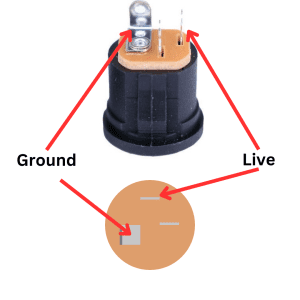
It’s pretty simple.
That third tab is used if you’re using a battery with the stereo jack. I’m in the camp that we shouldn’t be using batteries in pedals, especially DIY pedals. It’s wasteful. If you’re building pedals, go out and get a power supply and don’t go through the extra effort of wiring them for batteries.
Tying It All Together
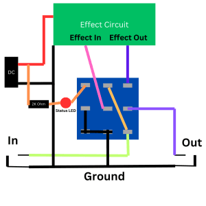
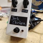
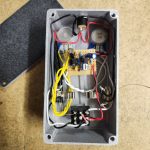
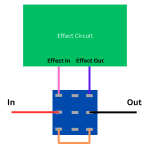
Of course the power supply is only one part of wiring a guitar pedal enclosure. There’s the foot switch, the input and output jacks, and, of course, the pedal circuit itself. Plus the status LED too!
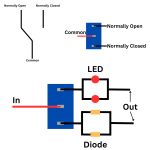
For the status LED, you can wire this directly into the live tab of your power jack (via a resistor), with the negative end going into your foot switch. It’s all like this:
 If you want a full rundown, here’s my article on how to wire a guitar pedal foot switch.
That’s It
I know I went into the background of guitar pedal power jack wiring a little bit, but hopefully at least a couple readers found it interesting. At the very least, you can be “that guy” at band practice who can bore your band mates with useless trivia.
Related posts:
 How To Wire A Guitar Pedal Foot Switch (3PDT)
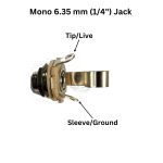 How To Wire 6.35mm (1/4″) Socket
 How Do Guitar Pedal (And Guitar) Volume Knobs Work?
 How Does A Drive, Gain, Or Distortion Knob Work?
 Why You Should Build Your Own Guitar Pedals
 Should I Make Guitar Pedals On Stripboard Or PCBs?
 How To Wire Guitar Pedal Enclosures
 What Is True Bypass In Guitar Pedals?
Is It Expensive To Make Your Own Guitar Pedals?
What Is True Bypass In Guitar Pedals?
Is It Expensive To Make Your Own Guitar Pedals?
 The Difference Between SPDT, DPDT, And 3PDT Switches And How To Use Them