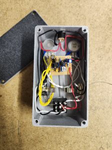
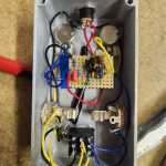
So you’ve finished soldering your guitar pedal circuit, you’ve debugged it and it’s working, so it’s time to put it into an enclosure. Well done.
Wiring up a guitar pedal enclosure can be a daunting task. It seems like the easy part after getting a pedal’s circuit working, but getting a pedal enclosure wired well is just important as the circuit itself; there are places where mistakes can be made. It’s also important that everything is tidy; nothing is better than a good looking pedal, and it also makes it easier to fix if you have a problem.
Personally, I have a lot of trouble keeping things tidy when wiring my enclosures. Having a really good looking build takes time and patience. I usually start off taking my time, but my patience wains after awhile. Like everything, it’s a skill. And it’s a skill I need to continue to work on.
I have articles dedicated to wiring each part of a pedal enclosure (footswitch, power supply, and input/output jacks) that I’ll be linking to in each section of this article, this guide is more about tying it all together.
So let’s start at the beginning.
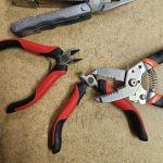
Drilling Out Your Pedal Enclosure
Drilling out a pedal enclosure is its own thing apart from wiring. I don’t think it warrants a whole article, but it’s worth addressing briefly.
Obviously you need to drill out the enclosure before wiring it. My tips for drilling include:
- Double check hole placement before drilling. The expression “measure twice, cut once” is true.
- Take your time. When drilling through metal, you often can’t just jump to a big bit and get it done quickly. Start with small bits and gradually work your way up.
- When one of your holes is big enough, cover it in masking tape so you don’t accidentally make it bigger.
After you’ve drilled out your enclosure, it’s time to paint it. Because of this, I prefer to drill and paint my enclosure before I start soldering my pedal circuit. This allows the paint and any artwork to dry in the meantime.
Thinking Ahead For Good Pedal Enclosure Wiring
 When soldering the input, output, power, and ground wires on your pedal’s circuit board, it’s important to think ahead.
This means making sure there’s more than enough wire available to make it to the part it needs to be wired to.
Personally, I like trying to have wires around the outside of the enclosure, so I leave a lot of slack to allow for this. This also means often overestimating the amount of wire needed for the end phase. This is fine as I keep my offcuts to be used for links and jumpers in the future.
If you’re going for a more direct wiring approach, you still need to think ahead in terms of how much wire you’ll need.
Basically, it’s always easier to make a wire shorter than it is to make it longer!
Wiring Your Footswitch
I won’t go into all the points on how to wire a 3PDT guitar pedal footswitch, I already have an article for that. But I usually like to start with the footswitch.
Some say to put the footswitch into the enclosure and wire it in there, but I think this is just making things harder than they have to be. I usually start wiring parts of the footswitch and then putting it into the enclosure when it’s ready.
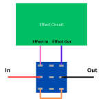
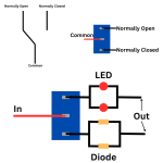
Here’s the basic diagram of wiring a footswitch (again, use the link above for a full explanation):
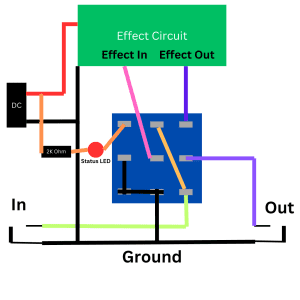
Before putting the footswitch in the enclosure, I’ll wire:
- The LED (dark orange wire), obviously leaving the end going to the power supply unattached for now.
- Connection between the second column and third column (light orange wire).
- Input wire (green wire). I do this in conjunction with the wire mentioned above to keep things tidy.
- Ground from the first column to the second column (black wire). Also keep in mind the wire coming out of the connection on the second column. Solder everything at once to make it easier.
- Output wire (purple wire on the second row of the third column).
From there, I usually then put the footswitch into the enclosure and move onto the next steps.
Think About Where Ground Is Going To Go
I was going to put this until the end, but here is where I usually think about where I’ll put my ground wires. Remember that ground is shared and all needs to go back to the ground of your power input.
I find it difficult to get more than two ground wires into the tab on the power supply, so usually I go:
- Ground from the circuit board goes to the ground of the output jack.
- Ground from the output jack goes to the input jack.
- Ground from the input jack goes to the power supply.
Of course, this will always depend on where everything is within your enclosure, what kind of enclosure you have, etc. What I’m saying is think about it and plan for it.
Wiring Your Input And Output Jacks
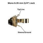
If you’re not sure what goes where, here’s how to wire guitar input and output jacks. These are pretty simple. If you don’t want to read the whole article, here’s how to wire them:
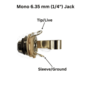
You need to screw the jacks in before wiring them. The main things to do are:
- Solder the input/output wires from the footswitch you’ve just wired.
- Assuming you’re using the ground wire set up I’ve mentioned above, solder in the ground wire that will go to your output jack and the ground wire that will go to your power supply.
- Solder the ground wire from your input jack to the ground tab of your power supply.
- Just make sure to attach the power jack to your enclosure first!
- I then do not solder the ground wire coming from the input jack into the output jack. I’m waiting for the ground wire from my pedal circuit.
Wiring Your Pedal Circuit Into The Enclosure
From here, it’s time to wire your actual guitar pedal circuit into the enclosure!
When wiring the circuit board into the enclosure I like to not screw the potentiometers in until last, this gives me space to work. Because of this, the order I wire things is:
- Solder the ground wire to the output jack, remembering to solder the ground wire coming from the input jack to the output jack at the same time.
- Solder the effect in and the effect out wires to the footswitch.
- Solder the effect power supply and your LED live end to your power supply’s live tab.
- Screw your potentiometers into place.
- Adjust wires as needed, everything should be attached.
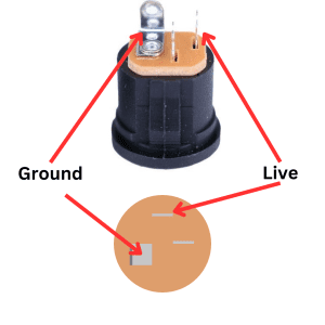
If you’re not sure which is which on your power jack, here’s an article on power supply wiring, with a picture below.

Other Tips For A Successful Pedal Enclosure Wiring
All of that is the order of how I wire/solder everything. Give it a go, but you may have a different order/method that works for you. For me, this is an order than gives me space to work while ensuring nothing gets in the way.
But, depending on the enclosure type you’re using and the way your circuit board is wired, you may find a better order to solder things. All that being said, here are my final tips:
- Think and plan ahead. As mentioned, this order may not work for every enclosure and build. Think and plan ahead on what will work best.
- We wary of creating shorts by mistakes and making contact with the enclosure.
- In tight builds, your circuit board may come in contact with the back of a potentiometer. A dustcover for your pots or a bit of tape can help here.
- Solder from wires attached to potentiometers can sometimes touch the pedal enclosure, a bit of tape over the connections can prevent this.
- Be gentle. If you’re new to this, some of your solder joints may be a bit delicate. It’s possible to dislodge things when getting them into place.
- Test your pedal again before putting on potentiometer knobs and closing up the back. Call be superstitious, but every time I’ve closed up a pedal enclosure before testing it first, it suddenly stops working! Test it, make sure your enclosure wiring is working, then close it up.
That’s it. None of this is too complicated, and probably something most people can piece together from my guides on wiring general enclosure components, but I figured I’d put this all together into a order to get people started.
Related posts:
 How To Wire A Guitar Pedal Foot Switch (3PDT)
 How To Wire A Guitar Pedal DC Power Jack
 How To Wire 6.35mm (1/4″) Socket
 What Is True Bypass In Guitar Pedals?
 How Do Guitar Pedal (And Guitar) Volume Knobs Work?
 How Does A Drive, Gain, Or Distortion Knob Work?
 Big Guide To Debugging DIY Guitar Pedals
 Should I Make Guitar Pedals On Stripboard Or PCBs?
Is It Expensive To Make Your Own Guitar Pedals?
Should I Make Guitar Pedals On Stripboard Or PCBs?
Is It Expensive To Make Your Own Guitar Pedals?
 The Difference Between SPDT, DPDT, And 3PDT Switches And How To Use Them