It’s time to get a little more in depth on transistors. If you haven’t read it yet, check out my guide to transistors for some background on how transistors work in guitar pedals and in general. This article builds on the general guide to explain saturations, active, and cutoff region in transistors.
The basics of this are:
- Active region: the transistor works as an amplifier. Here you get a bigger signal that should be relatively clean.
- Saturation region: the transistor is effectively overloaded. It amplifies while also working like a clipping diode, usually creating fuzz.
- Cutoff region: the transistor is basically off. This is no fun.
I’ll go into how these states are achieved, but first, let’s go through some background to better understand what’s being talking about in this article.
This Article Will Be Written About From The Perspective Of NPN Transistors
Rather than writing/explaining everything twice, I’ll be explaining everything for NPN transistors. However, it’s easy enough to convert everything to be for PNP transistors as well.
For example, in NPN transistors, the active region happens when Vc > Vb > Ve, for PNP transistors, this is flipped around so that Vc < Vb < Ve. Don’t worry if that doesn’t make sense yet, I will be explaining!
This all just has to do with how the current flows through an NPN transistor versus how it flows through a PNP transistor; i.e. it flows the opposite way in these two types of transistors, hence the flipping of the voltages.
Diagrams May Get Confusing
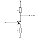
In researching and solidifying my knowledge on this topic, the diagrams get a little confusing. For example, the common diagram for an NPN transistor current is like this:
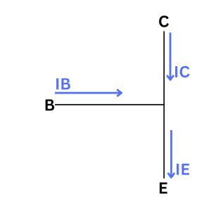
This makes it look like the current is flowing the wrong way, but it omits a lot of context on how this transistor would actually be wired.
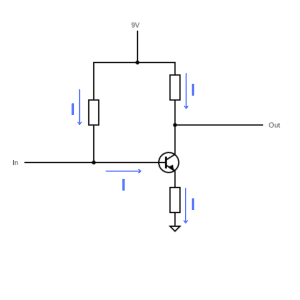
With the added context, we can understand what’s actually happening in the circuit and why the arrows are pointing where they’re pointing.
That being said, I’ll be showing diagrams “zoomed in” to just show the transistor simply. It may look like the current is doing weird stuff, but keep in mind the context of where the transistor is actually sitting in the circuit.
Active Region In Transistors
The active region (also known as the linear region) is what can be considered the “clean” region of a transistor. In the active region, a transistor is acting as normal amplifier, increasing the voltage and therefore for the volume of the signal in line with its hFE/Beta value and the amount of resistance on the emitter and the base of the transistor.
Here the voltage going into the base is less than the voltage at the collector but more than the voltage of the emitter. Or:
Vc > Vb > Ve
Just a reminder, this is for an NPN transistor. It’s flipped around for a PNP transistor.
This can be achieved when the emitter junction is forward biased and the collector junction is reverse biased.
In this setup, the current is amplified by the amplification factor (i.e. hFE/Beta) of the given transistor. Different transistors have different amplification factors, often something between 50 and 150, but it really depends on the transistor. Different guitar pedal builds will specify different transistors with different Beta values depending on what’s needed.
This gives us a situation like this:
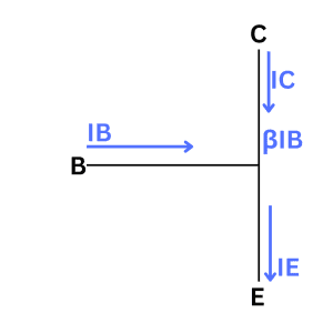
As an example here, if Beta is 50 and 2 mA of current is coming into the base of the transistor, 100 mA will come out, and it should be a clean signal.
Saturation Region In Transistors
To me, the saturation region is where things start to get fun.
In the saturation region of a transistor, the connection between the collector and emitter is basically shorted and the whole transistor starts to act like a diode, causing the signal to be clipped.
This happens when the base voltage is larger than both the collector and the emitter voltage or:
Ve < Vb > Vc
This can be achieved when both the emitter and collector are forward biased.
To go further on this, the difference between Vb and Ve needs to be higher than the transistor’s threshold voltage; this is similar to forward voltage in diodes, which causing clipping as well. The threshold voltage will depend on the type of transistor, but it usually causes a voltage drop of about 0.6 volts.
While pushing a transistor into saturation is as “simple” as putting a relatively high voltage into the base, it’s possible to overdo it and cause way too much clipping and therefore create a really truncated sound. All of this will be dependent on the exact kind of transistor, so it’s worth experimenting with the biasing to see what sounds you get.
Cutoff Region In Transistors
In the cutoff region, the transistor is off. It’s actually like there’s no connection, like an open circuit.
This occurs when the base current is less than the collector and the emitter current or:
Ve > Vb < Vc
This is achieved when both the emitter and the collection are reversed biased.
Generally speaking, we’re not interested in getting a transistor into the cutoff region, at least when building amplifiers or guitar pedals. I can imagine there are applications here if you’re having the transistor act as a switch, but that’s not the direction I’m heading here!
Let’s Summarise
As mentioned, all of the above holds for NPN transistors. If you want to know the region conditions for PNP transistors, you just need to reverse the voltages.
So, for NPN transistors:
- Active region: Vc > Vb > Ve
- Saturation region: Ve < Vb > Vc
- Cutoff region: Vc > Vb < Ve
For PNP transistors, it’s the other way around:
- Active region: Ve > Vb >Vc
- Saturation region: Ve > Vb < Vc
- Cutoff region: Ve < Vb >Vc
Other than that, that’s about it. Now go make things make noise.
Related posts:
 Ultimate Guide To Transistors In Guitar Pedals: What They Do And How They Work
 What Is Transistor hFE?
What Is Gain (And How It’s Different From Volume)
The Difference Between Silicon And Germanium Transistors
What Is Transistor hFE?
What Is Gain (And How It’s Different From Volume)
The Difference Between Silicon And Germanium Transistors
 Ohm’s Law: Explanation And Applications
 Ultimate Guide To Resistors In Guitar Pedals: What They Do And How They Work
 Ultimate Guide To Diodes In Guitar Pedals: What They Do And How They Work
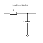 How High Pass And Low Pass Filters Work In Guitar Pedals
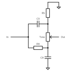 Understanding Mid-Scoops And The Big Muff Tone Circuit
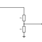 What Is A Voltage Divider?