Even if you’re just doing PCB kits or following strip board layouts, learning how to read a circuit diagram really comes in handy when building guitar pedals, or for electrons in general. So, if you stumbled onto this article with no interest in guitar pedals and just want to learn how to read circuit diagrams, don’t worry, you’re in the right place. I’m going to be going over reading circuit diagrams from a “guitar pedal point of view,” but this is all basic stuff that will apply to other electrical circuits as well.
Why Learn How To Read Circuit Diagrams?
It’s universally known that, when making a new guitar pedal, it won’t work the first time. There’s always something to debug. Even if you don’t have a lot of electrical knowledge, knowing what components are where in a circuit can help you zero in on where a problem may be; whether that problem is with the power source or the audio signal.
Additionally, understanding how to read a circuit diagram allows you to start being able to modify some of your favourite pedals. You can see what everything is doing and swap out components to make something sound truly unique! Maybe you want to adjust a high or a low pass filter? Well, you can if you know where to find it in the circuit.
Circuit Diagram Symbols
The key to understanding and reading circuit diagrams is knowing what each of the symbols means. From there, it’s mostly just a matter of following lines and understanding how they all work together!
The good and bad news is that there really are only a handful of common components used, and therefore not too many symbols you have to memorise. The bad part of this, though, is that there are a lot of uncommon components and, since you don’t come across them very often, you may not remember what they mean.
Since this is an introductory article on reading circuit diagrams, I’m only going to focus on the more common components.
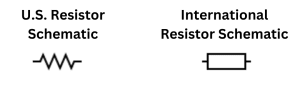
Resistors have two different symbols depending on whether the diagram is U.S. or international. Here they are:
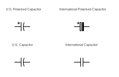
Capacitors have four types of symbols as well U.S. and international versions of polarised capacitors (typically electrolytic capacitors), and U.S. and international version of non-polarised capacitors.
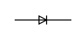
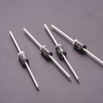
Diodes only have a single kind of resistor (for your standard diode at least!). There are some more exotic types of diodes out there, but let’s keep it simple with the basic diodes. The arrow in the symbol points in the direction of electrical flow. So on the symbol below, the positive is on the left and the negative is on the right.
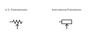
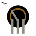
Potentiometers, which are basically just variable resistors, have bother a U.S. and an international symbol, similar to their resistor counterparts. While it’s obvious which one is the middle leg of the pot (it’s the one with the arrow), it can easily be confusing which is the left left and which is the right leg of the pot. If you just orient the physical potentiometer the same was as what it is in the schematic, just wire it like that.
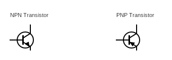
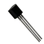
Transistors are another common component in wiring diagrams, and they come in two types: PNP and NPN. It’s important to use the right kind of transistors as specified in the diagram. The other tricky thing about transistors is that different models of transistors have different pin arrangements, even if they’re the same kind. So, for example two different models of NPN transistor may have their pins arranged in a different order. Check the datasheet if you’re swapping transistors.
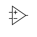
Operational amplifier (op-amp) symbols can be a bit tricky in wiring diagrams, especially because they typically have six pins, and your typical op-amp symbol only shows three pins. Like transistors, different op-amp models can have different pin arrangements.
Firstly, consult the data sheet for a given op-amp to understand what pin does what. Secondly, understand that if all six pins are being used, it’s a dual op-amp (it’s two op amps in one). So the symbol is for one side of the dual op-amp, or just a single op-amp if it’s not dual. Finally, the power supply for the op-amp is implied, although sometimes you’ll see connections coming in the top and out of the bottom for power/ground.
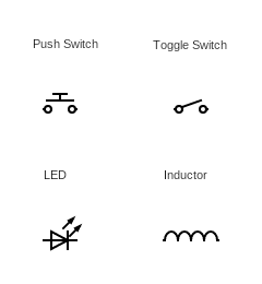
While there are dozens more other wiring diagram symbols, this articles is more of an introduction, so I’m not going to go through every single one. However, there are a handful more common components used in guitar pedal building and beginner electronics.
Reading Values On A Circuit Diagram
Components on a circuit diagram typically won’t just be presented on their own. Instead, they’ll have a value associated with them so that you know to use, for example, an 10K ohm resistor.
You’ll typically see values written near the component, a component number, or both:
If it’s just a component number, the schematic should also have a corresponding list of what values go with what components numbers. Personally I like diagrams that just give the component numbers because then you get of list of everything you need, and it’s easier to tick things off as you go.
You’ll also notice in the example above that the transistor is simply labeled as “Q1.” This is because transistors are usually named with a long string of numbers. It’s easier to just label them with a number and put the part number at the bottom.
Typical abbreviations for components are:
- R – resistor – measured in ohms/kilohms (k)/megohms (m)
- C – capacitors – measured in picoFarads (pF)/nanoFarads (nF)/microFara (μ or u)/Farad
- D – diodes – with a model number listed
- P – potentiometer – with a value listed
- Q – transistor – with a model number listed
- IC – integrated circuit (op-amp) – with a model number listed
Following The Circuit
From here it’s just about following the circuit, putting components in the right place, and wiring them together.
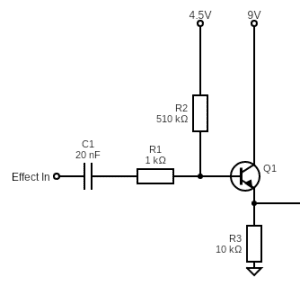
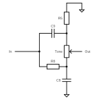
The challenging thing about converting a circuit diagram into an actual circuit is it’s not necessarily about just following a line. Using the example above again:
- There’s a three way junction between R1, R2, and Q1. There’s also a three way junction between Q1, R3, and the output.
- Three way junctions are denoted by a dot.
- Sometimes wires will cross. If there’s no dot, it’s not a junction.
- the 4.5 volt and 9 volt power supplies are coming from “somewhere.” There may be another part of the diagram not attached to this that shows how the power supply works, it may just be implied.
- A lot can be left up to interpretation. There’s a certain art in translating a diagram into a compact design that works. You don’t have to have a literal step by step approach as implied by the diagram.
- This is a relatively simple example, things get more complicated.
As with everything, don’t just jump into a really complicated circuit and hope you can find your way through it. It can be a bit of a puzzle and it’s a new langue. Start with simpler circuits. Try building these simple circuits on a breadboard to see how they work, then move up from there.
Some other final tips:
- Ground is treated as common. When making your circuit, make sure to only have one ground and attach everything to it.
- Remember that, although the diagram may look big on paper, it can likely be quite compact. Look for other commonalities for power supply.
- With that, look for opportunities to effectively fold the circuit back on itself. Don’t just travel from one side of your bread or strip board to another, weave up and down.
Hopefully this introduction of reading circuit diagrams helps you take the first step. From here, the best thing to do is trying to make something! Practice makes perfect.
Related posts:
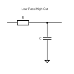 How High Pass And Low Pass Filters Work In Guitar Pedals
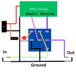 How To Wire A Guitar Pedal Foot Switch (3PDT)
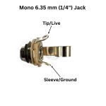 How To Wire 6.35mm (1/4″) Socket
 Ohm’s Law: Explanation And Applications
 Ultimate Guide To Resistors In Guitar Pedals: What They Do And How They Work
 Ultimate Guide To Diodes In Guitar Pedals: What They Do And How They Work
 Ultimate Guide To Transistors In Guitar Pedals: What They Do And How They Work
 Understanding Mid-Scoops And The Big Muff Tone Circuit
 Potentiometer Wiring: How To Wire A Potentiometer
 Gear You Need To Make Guitar Pedals