Part of building DIY guitar pedals is creating something that doesn’t work then figuring out how to fix it. This is all part of the process of debugging guitar pedal builds. These things are hand built, after all, and even experts make mistakes from time to time.
One of the common problems with a home made guitar pedal is no signal coming through. Just… silence. Personally, I find this a more re-assuring fault, as it’s usually easy to find where there’s a bad connection and fix it. If you’re getting a signal but it doesn’t sound right, there’s a myriad of reasons why and lots of things to check. If there’s simply no signal, it’s usually a matter of tracing the signal path with an audio probe.
So let’s look at how to trace the audio signal path in a guitar pedal and probe it to find a problem. In my article on how to make a guitar pedal tester, I explain briefly on how to make an audio probe, but I’ll go into a little bit more here before jumping into tracing an audio signal path.
How To Make An Audio Probe
Although this may sound sophisticated, making a simple audio probe is actually quite simple.
If no signal is coming through your guitar pedal, it’s likely stopping or getting lost somewhere. An audio probe allows you to bypass all of or part of your guitar pedal circuitry. By working and probing along the signal path, you can see where the signal is lost.
To make an audio probe:
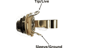
- Connect a wire to the live tab of the pedal output jack. I like the wire to be about 30 cm/1 foot long to make it easy to work with. If you have a dedicated testing rig, you can solder this wire to the output jack or just use an alligator clip.
- Using the other end of the wire, touch it different parts of your guitar pedal while playing the guitar. If you can hear sound coming through, that part is working!
- You may want to solder a capacitor to the probe to prevent DC from coming through. This will give you a cleaner signal, especially in areas near power sources.
With your probe, start at the input wire to your guitar pedal, then work your way along the audio signal path, strumming the guitar as you go. When you hit somewhere without any sound, it’s time to investigate.
The rest of this article will go through how to find the audio signal path for a guitar pedal circuit, as well as some other tips.
Finding The Audio Signal Path In A Guitar Pedal Circuit Diagram
When looking at a a guitar pedal circuit diagram, there are three broad categories of what a component does. First category is the path that the audio signal follows (this is what we’re interested in this article). Second is the power supply to things like integrated circuits and operational amplifiers. The third is “other stuff.” This is most draw down resistors, filters, etc. Obviously there’s a little more depth there, but if you’re trying to find an audio signal’s path, it’s easy to think of it in those terms.
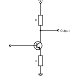
Let’s take a look at a relatively simple circuit. This one is for a ZVEX Super Hard On, which is known to be easy. I’ve put it on my list of beginner DIY guitar pedal builds for this reason.
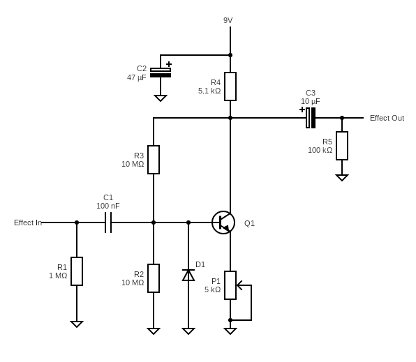
The way I like to look at things is using the following logic:
- The audio signal needs to start at the input and end at the output.
- So anything that goes to ground isn’t going to be the audio signal; this eliminates R1, R2, D1, P1, C2, and R5.
- Similarly, the audio signal isn’t going to follow a dead end that goes to the power supply. This eliminates R4.
So already, we’ve narrowed things down quite a lot! It just raises the question of whether the audio signal is going via the transistor (Q1) or R3.
- If you know what transistors do in guitar pedals, you’ll know they amplify a signal, so the answer here is the audio signal is going through Q1.
- If you didn’t know this, this is one of those ones where you need to test both. If you’re not getting a signal through either, you know it’s a problem with one of the two components.
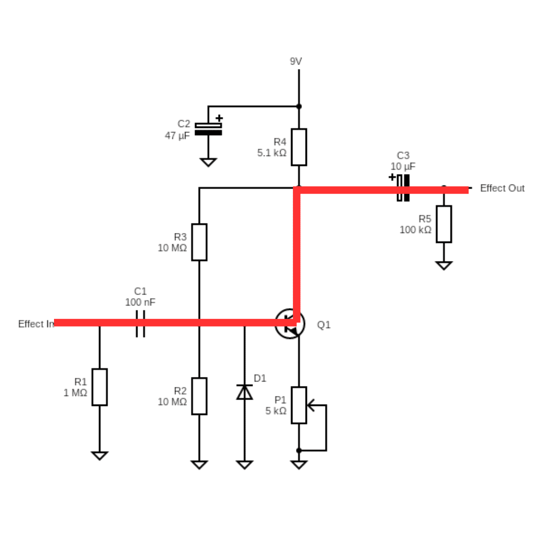
So here’s what the audio signal looks like for the ZVEX SHO:
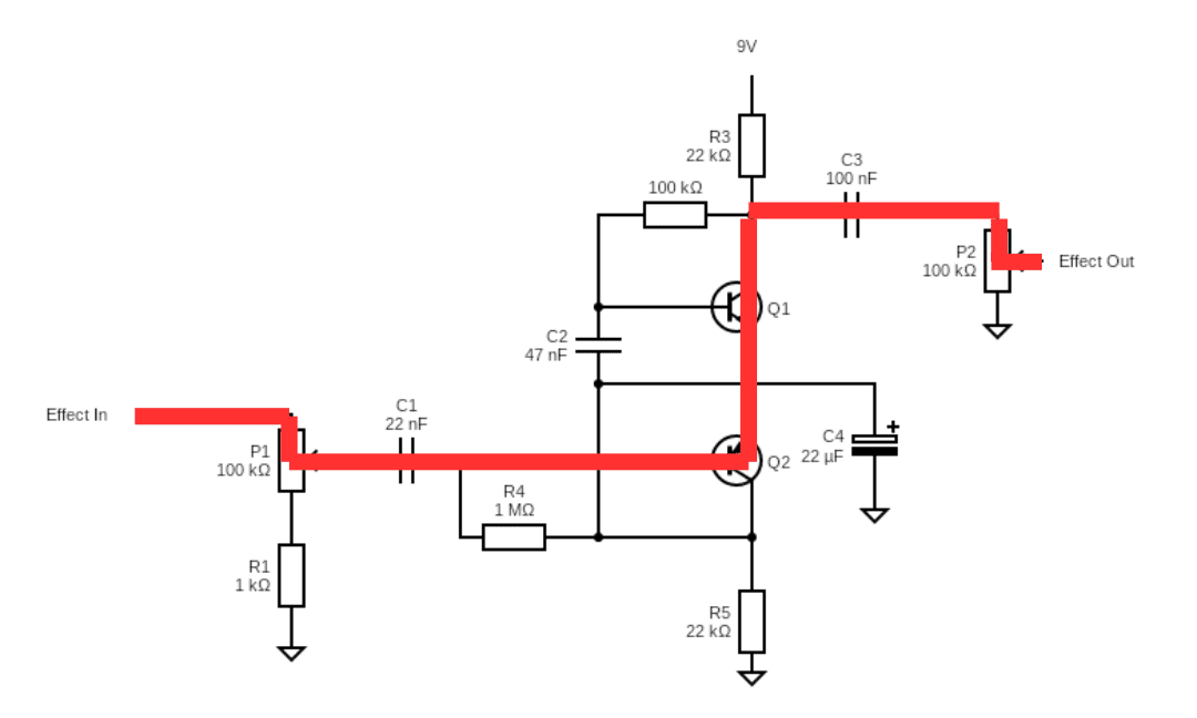
Let’s take a look at another example that’s slightly more complex. Here we’ll use another great beginner pedal, the Harmonic Jerculator.
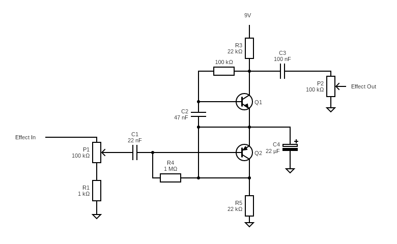
Let’s use the same logic as before:
- R1, R5, and C4 are out because they go to ground
- R3 is out because it goes to the power supply.
- R4, C2, and R2 are tricky are tricky, because these are conceivable paths, even knowing that the signal will go through the transistors (Q1 and Q1).
In this case, we can assume that the audio signal is going to take the most direct path, so it’s going to skip R4, C2, and R2. Again, if you’re unsure, you can probe all the potential paths and at least it narrows things down. So here’s the signal path:
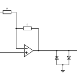
A Note On Op-Amp Feedback Loops And Audio Signals
Op-amps can be a little bit tricky because they often have a feedback loop. In this case, the audio signal will come back around itself. Take a look at the feedback loop for an Ibanez Tube Screamer.
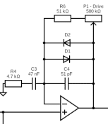
Here, the audio signal goes into the op-amp on the left and leaves it on the right, but it also goes through the feedback loop above. All these components need to be probed.
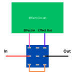
Finding The Audio Signal Path In A Guitar Pedal Stripboard Diagram
If you’re building your guitar pedals on stripboard, things can be a little bit trickier if you don’t have the wiring schematic as well. A PCB guitar pedal kit is usually a bit easier because the kit often comes with a schematic to follow. But stripboard, you’re just given the layout.
Let’s take a look back at the Harmonic Jerculator (this time on stripboard):
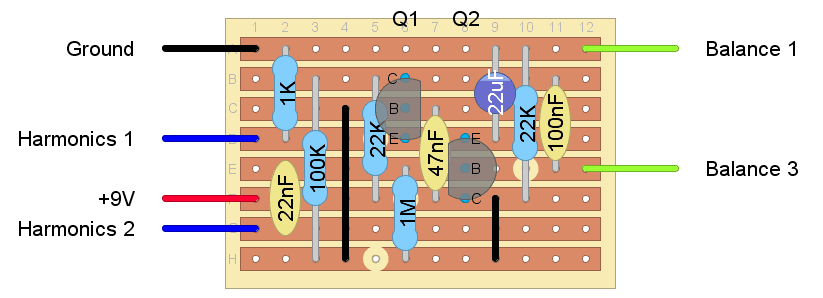
Let’s evaluate the layout:
- Row A is ground, so we can remove any components that go to it.
- Note that some layouts will have multiple rows/sections with ground. Look for links and cuts.
- Row F is the power supply, so we can also remove components going to it.
- Also remember that some layouts will have multiple rows with power.
- Be careful of cuts hidden behind components. The 1M resistor in column 6 sits in front of a cut!
- From there, you can trace the audio signal from the input just like you would on a schematic.

Other Tips For Probing The Audio Signal When Debugging A Guitar Pedal
With the audio signal path known, probing it is easy. Just:
- Strum your guitar and touch the probe to the input wire solder joint.
- Assuming you get a sound coming through, strum the guitar again and touch the probe to the next solder joint in the path.
- Repeat this until you find a spot where you’re not getting sound. It’s here that you should investigate for a bad connection, an incorrect component, etc.
But it’s not always as simple as the component you’re probing being the problem (unfortunately). A lot of the time, it will be a problem with that specific component, but sometimes it’s something near by.
- An incorrectly wired component with a high amount of resistance nearby could be pulling all of the signal but effecting the sound earlier in the signal path. I experienced this with my Purple Plexi build. The tone control potentiometer was incorrectly wired by causing a volume drop on the resistor before it because it was drawing so much of the signal.
- Transistors and integrated circuits like op-amps can be weird. The audio signal may stop abruptly at one of these and it may be because of a power problem, incorrect pin configuration, or a poor solder joint. But at least you know it’s probably a problem with that component.
- If you lose signal only after putting your newly soldered pedal into an enclosure, you also need to probe the input jack, probe the footswitch to make sure it’s wired properly, and make sure there’s not a short between a potentiometer or your board and the enclosure (a probe probably won’t find this).
Hopefully all of this advice will help you find the audio signal path for your guitar pedals and then successfully debug them. Some of this comes from experience, but you also need to start somewhere.
Have fun.
Related posts:
 Big Guide To Debugging DIY Guitar Pedals
 What Is Gain (And How It’s Different From Volume)
 What Is True Bypass In Guitar Pedals?
 How To Use A Distortion Or Overdrive Pedal
 What’s The Difference Between Symmetrical And Asymmetrical Clipping?
What Is Transistor hFE?
What’s The Difference Between Symmetrical And Asymmetrical Clipping?
What Is Transistor hFE?
 Is It Expensive To Make Your Own Guitar Pedals?
 How Do Guitar Pedals Work?
How Do Guitar Pedal (And Guitar) Volume Knobs Work?
How Do Guitar Pedals Work?
How Do Guitar Pedal (And Guitar) Volume Knobs Work?
 Transistor Saturation, Active, And Cutoff Region